|
|
Post by sime66 on Feb 28, 2015 17:56:20 GMT
It’s good to be thorough, but you’ve got to know when to stop, and I don’t need to make work for myself unless it’s needed, or going to be significantly more accurate; in this case we reckon I have it covered, and I don’t reckon the extra effort is going to be any more accurate. I do need the extra volume in the head above TDC, and as I had the barrel off I measured the crown, (some above deck, some below – I’ll do a quick scribble at half-time) so I can have a bit of a think about that one; maybe bolt the head on and do a volume measure for comparison/out of curiosity – don’t know. If I draw it as a solid, I think Sketchup will probably give me a volume. I’m not too worried about the volume measuring, and my linear measuring came out better than I expected too; it’s this base gasket conundrum that’s distracting me from the French and Welsh at the moment. Here’s a little half-time scribble:  [ At first I typed in m aniscus, ‘Word’ corrected me to meniscus; I typed in meniscu sses, ‘Word’ dropped the double-‘s’, so I ended up with meniscuses. As it happens, being of a curious mind, I checked after you asked and the correct plural is menisc i, so I should have stuck to ‘bowing’. – It don’t really matter as long as it doesn’t make you spill your beer! (or milk, or rum).]  |
|
|
|
Post by vespasco on Feb 28, 2015 19:58:47 GMT
The confusion was...in your previous figures you had 0.65mm DH with the 0.2mm gasket. Thats fine. Take off that gasket and you will have 0.45mm DH. Ok. (In theory at least but you can re check that to be certain). So if you then fitted a 2mm gasket your DH would be 2.45mm In your previous chart, with the 2mm packer, you had a DH of 2.65mm. I may be getting confused comparing the Lammy Port Calc to your calc, especially as i cant view them side by side, but it looks to me like youve also, in your calc, raised the exhaust port by 2mm (Height Over Port), just by adding a 2mm packer!? The H.O.P. remains the same if you pack the cylinder or not. Like i said, it may just be me not being used to your calculator and the results maybe the same anyway!? But i thought id better point it out just in case. Easy answer to the base gasket confusion is, yes, measure without the gasket! Then re-do your calcs. And er yeh, treat the 0.68mm DH as a misprint..i must have been looking at an old pic. Im not sure what the ridge seal is? Is it just the manufacturing thing, where the gaskets are pressed out on the produdtion line, producing slightly raised egdes. (Probably caused by blunt/worn tooling) While talking of the gasket, when you're playing with figures to raise the cylinder, try to stick to the gasket thicknesses that are readily available. (Unless you want to make your own out of stock sheet of your required thickness. Bit of a pita really). Your volumes... have you measured the the piston displacement? the squish volume? or the whole combustion chamber area, including squish etc? .... are your figures for Compression Ratio made from the head volume alone (ie - the combustion bowl cc + the squish band cc)// if so you need to do some more measuring. For your records only, it would be good to know the actual cc of just the 'bowl' of the head, aswell as the complete head volume. if youve not measured the actual combustion area volume, youll need to. You will need to lightly smear a bit of grease around the sealing/mating surface of the upper piston ring and the cylinder wall - this is to prevent oil seeping past, which would give you false readings. (youd put more in)! Your syringe, pipettes and attention to detail will be plenty accurate enough I also done all my measurements with the same type of easily available equipment....i was also lucky enough, totally by chance, to have it measured with a burrette with 2 stroke oil, in a 2 stroke workshop too and the measurements were the same. (+/-0.5cc). The plug volume can be and needs to be measured when working out your CR and CorrectedCR. As a guide only, a long reach will be around 1 - 1.1cc. take a look at this new (lovely)! Polini 225 kit...yes, me wants, me wantsesses it! blog.scooter-center.com/en/details-for-the-polini-221ccm-vespa-px-tuning-kit-for-60-mm-stroke-cranks/there is a reason...it shows and explains in typical at-first-unfathomable german fashion how to measure your combustion chamber volume to work your CR *(It started typing this about 4hours ago so i may have missed some posts)?? i got disctracted! |
|
|
|
Post by vespasco on Feb 28, 2015 20:35:45 GMT
yup! i missed your post sime... and i just checked this time to make sure theres no more posts, so..........
i have to say, i dont really like that method youre thinking off to get the height of the crown above gasket face. to get the diameter accurate would be very tricky at such an acute angle. Best to follow the SC link. or get the top end fitted with head, as mentioned earlier, sit everything so the plug hole is horizontal, and fill /measure with oil. to top or bottom of plug hole - deduct/add the (measured) spark plug cc as necessary to get your total combustion chamber volume.
For the sake of using sketchup, or just as easy, maths, youd be better off measuring the diameter of your piston with verniers. Then measure the piston crown height, which is possible in situ, using your verniers/depth gauge. similar to the SC version. that would only work if your piston crown was a true radius arc. (like, not flat at the top etc). Thats why, actually measuring the whole thing, assembled, at TDC, is a pretty accurate way, especially if you're using small pipettes too. Thats what it is! No nonsense, No maths, just simple measuring equipment. As it is! thats plenty good enough for vespas.
*to re cap on the base gasket, if there is still any confusion - measure your deck with no gasket and start again from there.
|
|
|
|
Post by pxguru on Mar 1, 2015 5:10:35 GMT
Quite a bit to catch up on here  Flywheel weight on this tune doesn't matter too much. Just fit the lightest one you have. You need to keep the transfers on the low side for a touring tune. I would say 123 degrees transfers is a good place to start. With those three exhaust ports opened out you are not going to need as much blowdown, as with a single exhaust port. The original DR has 25.8 degrees blowdown which is slightly sportier but 10 degrees off from real sporty . As the barrel port heights stand, with 123 degrees transfer it will be 172 degrees exhaust and that means 24.5 degrees blowdown. This is all good to start with. See how it runs and go from there. No need to move any ports at this point. You might lose 0.1mm when you sort the exhaust port top edge but that won't matter at all. The exhaust bottom should keep the same profile but just be moved to be flush with the piston at BDC. So my advice is start with a very easy to remember, 2.0mm of base packing (gaskets, packers and whatever else all in total). Well spotted on those lumps at the base transfers. They can come out. Start with the casings and then do the barrel to match. Bigger transfers at the base will improve it right across the range. All the edges facing the crankcase should be knife edged (not too thin on the bore wall though). A long shanked 6mm carbide cone will move this pretty quick but it will still take a while to lose all that metal. 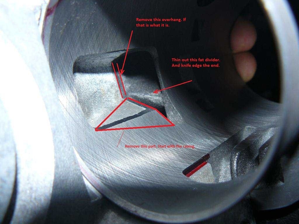 The other thing while still on dry build is to check how badly the piston ports line up with the barrel ports. There will be some work to do here. Once the deck height is set (expecting -2.45mm) you are going to need to lose quite a bit from somewhere. The squish clearance should be 1.0mm and no more. Easiest way will be to get the head on a lathe and cut it back 2.5mm to go inside the barrel. Check the head volume once you get this far. I expect the compression will be much higher than now but still ok. You will be looking for trapped compression of between 6.5:1 and 7:1. If it does end up too high you can modify it from there. |
|
|
|
Post by henri on Mar 1, 2015 6:50:34 GMT
vespaco ,i think your using paper base gaskets ,whilst the dr comes with a metal base gasket that is made with a raised line around the middle of its flat face, designed to crush down on torquing ,for belts n braces a very thin smear of ultra copper gasket goo in the channel formed before fitting it cases/down side ensures a strong seal , but sime it means you really need 2 gaskets ,1 to fit/measure with an a fresh 1 for final assembly , H
|
|
|
|
Post by sime66 on Mar 1, 2015 7:55:26 GMT
Blimey chaps; I catch a few hours sleep, and there’s plenty to chew on for breakfast. I’ll go into it - especially your numbers pxguru, which look encouragingly similar to mine, a bit later; I’m waiting for this downpour to pass so I can get out and ride, so just briefly: Thanks vespasco, I will do those volume measurements as described, and have another look at the link. I still say it’s trying to measure tiny volumes (half the crown = miniscule; there’s more sticky liquid up the side of the syringe/pipette/measuring cylinder) with blunt tools where the tolerances are greater than the volumes, but you clever chaps do it, and I’m a learner, so I’ll follow your advice – I’ll say no more because I’m grateful for your help. Thanks for the link too; I have seen it before, but only brushed over it then during an evening of Net browsing. I saw your video too, in case no else has confirmed the link works; I'll read your thread later - blimey, she is a beast!  I’m glad you chipped in pxguru; you seem to have saved me work in one area and found me work in several other areas, but on quick reading, it all seems doable. I’ll have a better look at the numbers later, and the other areas of investigation as I go. I still need to do some learning on some of the volume/compression stuff you and vespasco are talking about now too; I’m not familiar with that stuff, just tried to follow you two before on the other thread, and I’ll have to go through it at a Learner’s pace – for me, to learn – which is why I’m doing this. Henri, that’s exactly the gasket, it is intended to crush, they are so flimsy that I realised I was going to need a few spares if i do use them with the spacers. If you chaps go back a page to my post, Feb 26, 2015 at 5:59pm, you’ll see that I was asking about spacers then, to try to keep to standard, available thicknesses, and I linked to a few and asked if I was looking at the right thing; that question will become relevant soon, but I’ll add this - do I still use a gasket with these spacers? Chaps, the sh*te weather has passed; I have to get out to do a few checks and bits, I’ll get back to it later. Thanks for everyone’s input – very much appreciated. |
|
|
|
Post by pxguru on Mar 1, 2015 9:17:11 GMT
For the base packers I have some sheets of aluminum of various thicknesses and just cut my own. Best off with a single 2mm packer which is very convenient, as there is a 2mm sheet. Decades ago we just used to fit like 10 standard gaskets. Works fine but really looks bad With one thick packer it can be fitted and clamped up, when you are sorting out the base transfers and the casing, barrel and packer can all be ground to fit together while doing each casing half. When opening the base transfers there is no such thing as too big. The contact patch of the base to barrel only need be a few millimeters to seal (if you can be bothered to grind out that much). With the head, just get the squish right. The compression will be high but I am guessing not too high. No harm in measuring it to check once the head has been machined but this is fine tuning once it has a few thousand miles on it Edit; If you have time try to get some "up skirt" pictures of the piston! See how it lines up with the transfers at BDC. |
|
|
|
Post by vespasco on Mar 1, 2015 10:20:46 GMT
Im glad you suggested 123° transfers guru ji. Was worried 124°/8000rpm was too much for simes needs....(mine is tuned/restricted to less than 8000rpm and id rather it not go higher as it will startb to comprimise the low/mid range power). And with a 2mm packer you get pretty damn close to the 123°/7500rpm/171° Which leaves the squish/compression.. And porting the bottom of the exhaust port and tidying up. Theres no paper gaskets in my selection. All ali. Some stock @ 0.2mm thick and some cheapo ones @ 0.1mm but none with any crush ridge on them! Im not so sure i even remember seeing those kind before? Just use one gasket/packer if you can. The less gaskets/packers you have the chance there is of a leak and the more accurate you will be when measuring(less gasket paste). I imagine youll have to make your own if you want 2mm. Make 2no. X if you do , (1 X for another time). So if you are going to use a 2mm packer, i would start your measurements with no packer at all. The crush gasket you have will only confuse things! Especially if youre not actually going to use it! Yeh! Lets see some upskirt shots ;P hahaha |
|
|
|
Post by sime66 on Mar 1, 2015 12:00:36 GMT
Right then chaps, it’s starting to come together and make sense, thanks for everyone’s input; here’s where I’m at. I’ve put the barrel back on with no gasket, I can slip 0.25mm feeler in, and not a 0.3, so I’m pretty confident that 0.25 is accurate. (0.4mm NOT-crushed base gasket removed). All other dimensions from the same datum (barrel face) still apply, so my previous Friday barrel measurements are still good. Adjusting the Static Deck Height to -2.45mm, I get the same results as you do, which is: T = 122.95º E = 172.17º B.D. = 24.61º I’ve checked in both calc sheets, and we all agree. · It does give silly-big squish though, but no doubt we’ll overcome that with some magic-lathe trickery later. · Numbers for compression – dunno; give us a clue – I’ll do some reading. · There’s a big chunk to get the bottom of the Exhaust to B.D.C., but it needs a tidy anyway. (Same profile, or flat bottom?) The top just gets a tidy. · It also means that I’d like to use a 2mm spacer and 0.2mm gasket, if that’s OK – I might as well ask this now; gasket between barrel-spacer, or spacer-casings, or both, or neither – remember I’m aiming to get 2.2mm, not 2.0mm. I’m happy enough making my own spacer from sheet, and it makes good sense to do that to match exactly my modified casings – do it all together, as you say, but it isn’t just 2.0mm sheet. I’m going to put some drawings and stuff here now, to help me remember later if I need to refer back to it; you chaps don’t need it, but it helps me keep track. I started the drawing last night whilst going over the gasket thing with vespasco, so I’ve just changed it to suit what was said this morning; might as well have it:    vespasco, this is the sort of gasket we’re talking about – it might not be relevant now, but I photographed it last night, so you might as well have it for your memory bank:  Before putting the barrel back on, I had a very quick look at that transfer I highlighted before, and you picked up pxguru; just mainly to see if there were any problems with any of the bits that need removing. I see no problems with doing it, and I know we like to open it all up! It’s only a rough mark-up and photo, just to get my head round what needed removing, but as you wanted a bit of up-skirt vespasco, here you go:  incidentally, as you mention it pxguru, that little extra bit of transfer on the barrel is supposed to line up with a little round port on the piston, which I will check for alignment when I have a good look at the piston. All the other tidying, opening, knife-edging needed is noted, and more opening base transfers later; see how it all goes – I will have a good look at the piston ports matching the barrel too; should be interesting… I think I’ve covered everything that’s come up. I’m going quiet this afternoon, but I’m happy with where this is going, with a good combination of hands-on, calcs, and theory; it’s good learning for me; we might even end up with a decent engine too! |
|
|
|
Post by pxguru on Mar 2, 2015 6:53:03 GMT
2.2mm packer it is then. We all seem to agree From your -2.45mm port map something is not right. It might be just how you drew it but the shape of the port is upside down! The flat in the centre should be at the top of the port and the bottom should be full width (like it is now but a few mm lower). This is a big deal. As you have drawn it is not suitable for anything normal You are right, the side round holes in the piston is what I am getting at. Ideally they should be at least half open before the piston crown opens the transfers. I think if they do line up they will not be open enough. I guess they will each need elongating 5mm or so in the piston (lighter too, bonus!). And maybe a width correction to line them up. Its the same deal for the big side cut outs in the skirt. They are normally ok though and the barrel side cut outs are good so might just need rounding off the sharp edges and that's it. Those three boost ports are going to need some work too but I think you have enough to be getting on with for now! |
|
|
|
Post by sime66 on Mar 2, 2015 9:28:23 GMT
(Freezing - just got in; it's been snowing and blowing this morning!  ) )Righto; easy to tweak on paper, can I clarify which transfer Port width I’m matching? I’ve done a quick mark-up of my barrel rubbing to show you what I mean – there’s a few to chose from. I’ve also done a revision to the exhaust port sketch showing the whole profile dropped to BDC for the new Deck Height, and the width I’m querying for the flat top - I’ll get the exact width from measuring the correct Transfer on the barrel; these are just to show you the source of the measurements; which one I want to match:   I’m going to concentrate on my piston ports later today; it was only when I read back through the thread this morning that I picked up your edit about looking/photographing up-skirt. I sort of missed the point of vespasco’s note because i hadn't seen your's, but I’ll do it next. I’m going to order several squares of 2mm aluminium sheet this morning (to make a few, and bugger-up a few); does it have to be anything special? If not then they’re pretty cheap to play with: www.ebay.co.uk/itm/151241799135?var=450284058164Would it be a good idea to have a 0.1mm gasket both sides of this (to make up my 0.2mm)? So that all the metal-to-metal has a gasket? In other words, what’s the best way of using my 0.2mm? I saw the note about just using one, but that raises the previous question about which side ('or both - or neither' as above). There’s plenty to play with, cheers chaps……………..
|
|
|
|
Post by pxguru on Mar 2, 2015 15:37:27 GMT
My vote goes to "None of the above" 'A' has the right dimensions but the one crossed out the other way up is the closest in shape. 17.7mm flat across the top and blend in the corners. The bottom edge should be wide and low. If you start with the base transfers after your practice sessions on the H barrel, there is no harm done if you slip and mark the bore down there. I would use one 0.2 gasket toward the casing with a thin film of silicone sealer on each join. Less joints to pressure test/leak too. Lot of work to do. Going to take a fair while to get it prepared but it's going to be very different to the current engine |
|
|
|
Post by sime66 on Mar 2, 2015 17:10:12 GMT
I’m bound to get this shape right if I keep at it. The left sketch shows the opening in the barrel as it will be before mods; this much we are stuck with - it’s the existing port at the new height:  In the middle, sketch ‘C’, shows the 17.7mm flat on the top radiussed into the existing, ‘D’ is just to show more of a radius in case that was the problem with the top – but keeping the 17.7 flat; to get the shape (like the upside-down one) I’d have to raise the top more, previously I was trying to raise it as little as possible; I can’t go inside the dotted line – this sketch shows it raised 1mm, is that OK? Should I do more to get the shape? What’s the limit? Raising that is obviously changing my Exhaust timing; to get a better shape I’ll have to raise it more. My sketches ‘A’ & ‘B’ showed the bottom lowered to the new B.D.C., but with the same profile as the existing port. I can make the bottom flatter and wider, like these two new sketches, up to the width of the port with just a radiussed corner if that’s best, but if not then what width of flat at the bottom do I want? I see what you’re saying about doing the base transfers first – I’ll be doing the transfers in the cases before those too I believe? Noted about the 0.2mm base gasket – thanks for that. I’m not worried at all about how much work there is to do, as long as I’m clear on what I’m doing, and fairly confident I’m not going to bugger it up; there is no time pressure at all either, so I’m quite happy taking plenty of time to get it right on paper, and to take care with the actual cutting when I get to it. Not to drag up old debates, but it’s going to be interesting to compare my bunged-on DR180 with one that’s had a little tweaking, but that’s a long way off yet……… Edit:I just had a quick look at the exhaust timing if I went up 1mm; I make it: E = 176.25º B.D. = 26.65º  Don't know if that's right, don't know if that's alright - just thought I'd mention it |
|
|
|
Post by vespasco on Mar 2, 2015 23:26:05 GMT
Hang on, the ali sheet. Were you looking at the 120mm x80mm sheets? Are they big enough? (They may be im not sure, just seemed a tad too small to me)!? You could always go see your engineer and ask for some off cuts?
I vote top of port like C and bottom like either A or B
But by how much do you intend to raise the exhaust port!? Using the guides only its slightly over for 123° now. But im sure youre aware of that... Which is suited to BD @ 24°.
First is getting the transfers. This is then matched to the BD. Its these 2 which give you the exhaust duration. Raising by 1mm gives BD suited to roughly almost 125° /8700rpm!
Playing with the figures and 2.2mm is certainly the way to go to get transfer and BD to somewhere very close! Anymore or less and the Transfers amd BD seem to dramatically in/decrease.
Rule of thumb, i 'think' its fair to say, each raise of the exhaust port lowers the mid range power.
Is it? Its quite possible i may have missed something already mentioned on that subject.
There is also something else that confuses my poor ol' brain sometimes ... How does skimming the cylinder affect the timing and how does a negative deck head affect measuring the DH/timing!?
I also cant really remember the effects of too much BD! Its been a long week... and its only monday.
|
|
|
|
Post by sime66 on Mar 3, 2015 4:17:51 GMT
I've already checked the sizes; it was the grade/spec I was double-checking if necessary. 100x100 is big enough; there's 125 & 150 square too - all cheap enough as long as it doesn't have to be anything special. I can get a bit of tubing too from same supplier to make some sleeves, which I think I'll need for checking installed dimensions later.
I won't be cutting nuffink until we're all agreed with shape and dimensions:
Shape:
Waiting for responses to C & D which hopefully incorporate previous comments, guruji didn't like bottoms on A & B - those are already rejected, so I've gone flat and wide. The tops in C & D are trying to get the right shape without adversely changing Exhaust timing; I've queried how high is too high.
Dimensions:
Bottom is B.D.C.
I've made the point that raising top increases timing and shown how it is difficult to get the shape without doing so. In A & B I kept the increase to a minimum. I've used the example of 1mm giving 176.25º as an example, not a suggestion. I've done other figures too, but don't want to post loads until I get some feedback about the shape. I think we'll settle on 0.5mm (0.45 gives 174º, which was the first number we were aiming for when we were looking at 124º Transfer, but I very much doubt I can cut or measure the difference between 0.5 and 0.45!) I ain't clever enough to judge that height for myself, which is why I asked the question in my previous post.
Your other stuff I'll read properly in the morning; I'm in bed on my bluetooth keyboard, squinting at a screen too far away, but I heard my 'phone bleeping a couple of times and decided to reply, hoping that the early shift have something for me later this morning, for me to chew on during the day.
zzzzzzzzzzzzzzz
|
|
|
|
Post by sime66 on Mar 3, 2015 5:18:18 GMT
You need to keep the transfers on the low side for a touring tune. I would say 123 degrees transfers is a good place to start. With those three exhaust ports opened out you are not going to need as much blowdown, as with a single exhaust port. The original DR has 25.8 degrees blowdown which is slightly sportier but 10 degrees off from real sporty . As the barrel port heights stand, with 123 degrees transfer it will be 172 degrees exhaust and that means 24.5 degrees blowdown. This is all good to start with. See how it runs and go from there. No need to move any ports at this point. You might lose 0.1mm when you sort the exhaust port top edge but that won't matter at all. The exhaust bottom should keep the same profile but just be moved to be flush with the piston at BDC.- Lower the bottom to B.D.C , but keep the same profile - Raise to top just enough to get the flat C & D incorporate the comments on A & B, but in doing so do deviate from this above - particularly how much can I go up by to get a good shape, which I have queried. 0.1mm is pretty much what I drew in A - just enough to tidy and get flat, C & D go higher, hence the query. |
|
|
|
Post by sime66 on Mar 3, 2015 7:08:04 GMT
An extra topic – still need to sort the exhaust though, but I’m off for a while, so thought I’d get this posted before I get on…. This is what I was doing last night before I went back to the Exhaust port shape and size. I know it doesn’t replace doing a proper inspection and some upskirt photos for-the-lads, but it might give an indication of where there’s no worry, and where closer inspection or work might be needed. I’ve shown the vertical alignment of the piston ports with the barrel, and also the horizontal positions with piston at T.D.C., B.D.C., and T.O. I think I see where you reckon the little round piston ports need to be deeper; I think I can be more precise about the 5mm with a proper inspection, rather than just using my rubbings (probably less – I think I understood it should be half-open at T.O.), I’ll do that later, but I’ve just put my barrel back on, and don’t want to take my piston off yet, so it’s staying put until we’ve finished with jobs where it all is for a bit. Maybe these are useful for you, or they might point out something I might miss, maybe they just helped me associate piston ports with their barrel ports; anyway, here they are:    (Ignore the shape of the Exhaust port – still undecided) |
|
|
|
Post by pxguru on Mar 3, 2015 7:44:10 GMT
To make it easy let's go with 'A' on the port shape. The basic shape of the original is not drawn so well but the idea of 'A' is correct. Flat at the top and same profile but lower at the bottom. The 17.7mm flat at the top must come out of what metal is there. Under no circumstances should it be raised more than the accidental 0.1mm for polishing. Can't put the metal back later. I think 172 degrees is plenty enough for your needs. And without a big boys exhaust you don't want too much blowdown (24.5 degrees is the max for now).
Very useful diagrams for the port line up. 5mm drop on both of the piston side holes looks about right. The transfer slots in the bottom of the barrel should go full width of the main side piston cut outs too. And then angle up to the cut out from there. They will need to be dropped a few mm lower too to compensate for the barrel sitting higher.
Plan is coming together. You should get some of this cut before moving on
|
|
|
|
Post by sime66 on Mar 3, 2015 17:06:34 GMT
Here we go then, not had much time to do this today, so just a few bits to add quickly. Henri, the barrel arrived this afternoon, and I’ll have a jolly good look at it after it’s had a bit of a Gunking. That’s really good of you; thanks again - may all your wheels continue to spin freely. My aluminium sheet should be here in a few days too. I’ve been thinking about how I’ll cut it; would a fretsaw be the way to get most of it trimmed off before the precise matching? I’ll probably need to buy something, but I don’t mind buying tools. I’ll do a really close measure, photo and sketch of the Exhaust port before I actually cut it; I think we’ve got as precise as we can from the rubbing. If I do use 0.1mm I’ll get: E = 172.58º B.D. = 24.81º Is that acceptable? I do understand that this is the absolute limit, and will be very careful:  I’ve had a little play with these Transfer ports and the skirt, hopefully based on what you said; it might not be as much as I’ve shown when I’ve actually got the piston and barrel overlaid, but this is what I think you mean pxguru – ‘F’. Open the barrel to the skirt cut-out width, and then with the shape to the extra transfers, and then cut the casings to match the barrel. Also drop the bottom of the Transfers the same amount as I’ve raised the barrel (2.2mm) – does that apply to the third one too, or just the two with the skirt cut-outs? There’s the other two round ones that need lowering too, and maybe some little bits more when I actually get metal to metal, rather than the rubbings, and have a proper look when I take the piston and barrel off. Here’s a little sketch; tweaking’s no problem if needed:  It’s going to be cutting time soon enough. Stand back and count your fingers………………. |
|
|
|
Post by vespasco on Mar 3, 2015 20:27:50 GMT
Im following with interest. All good info. Theres not much i can add really. Seems you got it all covered. Just keep the top of the exhaust port as low as you possibly can! Good luck and keep your fingers out of the way! |
|
|
|
Post by sime66 on Mar 3, 2015 21:06:11 GMT
You asked some interesting questions last night vespasco, that we haven’t covered yet; we’ve just got on with deciding what I’m doing with my casings, barrel and piston. I’d quite like to have a look at your questions too, to get a better background, and see why those timing figures this morning were so crucial, but have been a bit busy today and I will be until the weekend really. The points/questions you raised were: 1. Does raising the exhaust port lower the mid range power? 2. How does skimming the cylinder affect the timing? 3. How does a negative deck head affect measuring the DH/timing? 4. What are the effects of too much BD? We might find time to sort some of it out. The only ones I can have a bash at are 2) & 3), and I’ll probably only state the bleedin’ obvious anyway: Timing is relative to TDC, not DH. DH just serves as a reference point to measure to, and the +ve or –ve DH just positions DH (reference point) back to TDC. So DH itself doesn’t change timing. The +ve or –ve DH is just a number in the calcs to add or subtract from port heights to get them relative to TDC. For example on my barrel I’m raising the barrel (and therefore DH), to get my ports right relative to TDC, but I’m then readjusting DH, but that’s not to change the timing; that skimming is to sort compression and squish – nothing to do with the ports or timing. That might be right or wrong, or too simple, but it’s how I think of it. - When the cylinder is closed-up and working, the DH is just a join in the barrel, not any relevant point. 1) & 4) are knowledge/theory/experience, and I’ve been a bit lazy with the theory since I got some bits of old metal to play with, and I don’t got no experience of none of it! There's no hurry anyway, - plenty of time to do a bit of theory; all this cutting is going to take me ages............. |
|
|
|
Post by sime66 on Mar 3, 2015 22:20:48 GMT
I'm just having a bit of a read, comparing my numbers with the tables, and just checking we're still OK:
Transfer Exhaust
RPM Duration Duration Blowdown
10,000 128 192 32
9,000 126 183 28.5
8,000 124 175 25.5
7,500 123 171 24
7,000 122 167 22.5
6,000 120 158 19
My numbers:
7,500 122.95 172.58* 24.81*
* = using the extra 0.1mm on top of Exhaust port
I guess this is because of the options left open to us by deciding that my novice hands shouldn't mess with raising all the Transfer ports.
Otherwise, we'd have raised the barrel less, and played with the Transfer and Exhaust ports relative to each other to get the right durations.
So, I know you'd have said already if it wasn't, but I'm just checking we're still OK.
It's vespasco's questions have got me thinking more about what the numbers mean from the point of view of what's happening in the cycle.
It's also given me a better idea of the process if we weren't making allowances for my 'special skills'.
That'll do for tonight, it's got me thinking about it a bit more now though.
|
|
|
|
Post by pxguru on Mar 4, 2015 3:58:49 GMT
So now you have A, F, and G all correct. Understanding my descriptions first time now! Boost port doesn't need any work as long as all those slots in the piston line up. Looking forward to seeing the photos of the finished job. Make sure you get yourself some decent safety glasses and always wear them before the tool is running. The metal swarf flies everywhere and your face will be right up close to it. My thoughts on the answers to the questions; 1. Does raising the exhaust port lower the mid range power? If the transfers are correct and are not moved then, yes. If the blowdown is too small for the transfers then raising it could increase mid range. 2. How does skimming the cylinder affect the timing? Doesn't 3. How does a negative deck head affect measuring the DH/timing? Doesn't 4. What are the affects of too much BD? Depends what you want from the engine. More blowdown usually gives more peak power at a higher rpm over an ever narrower rev range but at the expense of everything else (ie. torque, reliability, fuel economy, cooling). I like the way you added 7500 rpm in the middle of that table There are several of these from various books and sources. As we get further from the sixties these durations tend to get more accurate. This one just shows minimum durations. And that's where you need it. Trying to keep this whole thing more simple for you and everyone else who might want to copy you. When tuning for speed it gets a lot more complicated. |
|
|
|
Post by sime66 on Mar 4, 2015 8:33:14 GMT
Simple is good for me! ‘Tuning-Lite’ for Special Skills.
I’ll have a bit of a background read too, and try to keep some of it in my head, but from your answers my picture of Blowdown is this:
With reference to the table (this one above shows minimums – and I’ve slipped one in for 7500; others/later versions might be more suitable for other engines), increasing the BD (raising the Exhaust port top), only up to the minimum for the correct Transfer timing, will give an increase in mid-range power. Increasing the BD more than the minimum for the correct Transfer timing will reduce mid-range power, increase peak-power at higher rpm, but will also be detrimental to all the things I care about - (examples: torque, reliability, fuel economy, cooling). For my mid-range power/torque needs the minimum shown in the tables is also the optimum.
(I note what you say about the peak-power rev range narrowing with higher BD too, but that’s not something I need to worry about this time – there’s undoubtedly lots of other factors in the full version of ‘Tuning-Pro’).
So as long as I’m using the right tables, we get the Transfer duration right for the job first, and then get the Exhaust duration right for the correct Blowdown for the Transfer duration. (Exhaust duration is just the result from getting the Blowdown right). We’ve looked at Inlet timing already (for the engine type, the BTDC/ATDC and Ioº relative to Tcº), so that’s in the memory bank (or at least recorded here for later reference), so for ‘Tuning-Lite’; simple for Special Skills, we’ve got the port timings right on paper!
Whether we get them right on metal, only time will tell……………………..
(and that is plenty of time – not rushing; I’m afraid there’ll probably be many more ‘before’ photos yet – the ‘after’ photos might be a while yet – gotta bugger H’s one a bit first too!)
Probably not today, but next I reckon I’ll re-double-check my measurements for port heights now I’ve got no gasket, and then take my barrel and piston off to get a better look at them, while I’m waiting for my aluminium.
I’ll also be looking at the barrel and head skimming dimensions to make sure that end of the job is OK before cutting anything – it worries me a little. Actually I’ll measure the squish before taking the barrel off to get that started. Even though we know it’s going to be bleedin’ huge with the gaskets without the skim. (That’ll kick the volume/compression measuring/calcs off again too, vespasco).
Blimey! Lots to do.
Shall I use a fretsaw for the guts of the gasket cutting? It might be a simple question, but knowing what you chaps would do will help me get going with it. If that's the way, I need to buy some stuff.
|
|
|
|
Post by sime66 on Mar 4, 2015 8:59:48 GMT
.....So, after the measure and calcs, this is the target:  |
|
|
|
Post by henri on Mar 4, 2015 9:12:19 GMT
blimey sime ,i hardly know ya , you aint "buggerin h's 1" of anything , at least buy me dinner n flowers first , an i thought you was a gentleman . H
|
|
|
|
Post by sime66 on Mar 4, 2015 9:15:33 GMT
Not that sort of Rudeboy!
|
|
|
|
Post by pxguru on Mar 4, 2015 12:12:14 GMT
Looking at these numbers and if it all goes to plan in the metal, you might be hiring it out to plough feilds |
|
|
|
Post by sime66 on Mar 4, 2015 12:17:33 GMT
That doesn't sound very encouraging, - do we need a tweak?  |
|
|
|
Post by sime66 on Mar 4, 2015 12:52:20 GMT
I think you’re playing with me though. On my old baby outside, using the MicroDyno results from last year, my max power was at about 6,500 rpm. I think we’re looking at moving that up to nearer 7,500 rpm (123º) without messing up the low-end power for ploughing. (I'm not sure how we predict the NmMax/rpm, or the max rpm - lots of MicroDyno in the Autumn). So that’s good isn’t it? (for what I want – not selling turnips). Here’s the summary table; from December 6th off the MicroDyno thread (I know there was much tweaking afterwards, but I only did one lot of test rides, and that’s what I got):  Here’s my gear/speed/rpm table for my new engine/tyres/gearbox (when I get a bleedin’ gearbox) I think my max power should be at about 10mph higher, but I'm still climbing hills nicely with the opened Transfers and casings to suit - (and the Inlet and Blowdown as near to right as we can):   |
|


 )
)


