|
|
Post by vespasco on Feb 6, 2015 20:26:24 GMT
Theres no harm using old bearings for measuring/dry build. Pulling the crank in is relatively simple, especially with the right tools yeh but there are other ways that are just as good...even using your clutch if needed...its getting it out without knocking the crank thats more of a problem for most enthusiasts! For that you need a crank 'pusher'...*Edit - add pic....  Easy to make yourself but unfortunately only if you have access to a welder etc... Id suggest getting on your scooter one day and visiting your local engineering shop. Ask for an off cut of 10mm steel, 200mm x200mm is plenty big enough. Buy a coarse threaded HT nut and bolt, around 1/2" is ok. Prepare it all yourself, drill the holes if you can, then ask your local shop to weld the nut to the plate.. That should only cost a few £/the price of a drink if they're not grumpy ol' sods! You could also enquire about turning down your head/crank etc if you dedcided to go down that route. Theres room to take off 3mm from the top, thats not a problem. (Shave the fins down too) You could be really clever and turn down the cylinder in such a way that the squish/lip on the head recesses into the cylinder gasket face, making a self centring head! (I dont mean the combustion chamber sitting inside the cylinder - i know its done but id not rate it) If youre going to be doing the porting yourself, i recommend a good little head/torch and a magnifying glass/jewellers loupe (and safety glasses)! These 2 things will also help your accuracy when measuring too. The more you measure, the more accurate you will be! I see you dilemma tho'. Thats quite a bit of porting working to do, especially if youre not too confident. Maybe the money for new tools could go towards paying someone else to do the cutting etc instead? (Im going to try to scale off your drawing and measure to the bottom of your exhaust port/s. Ive got 9 lives) |
|
|
|
Post by sime66 on Feb 6, 2015 20:43:00 GMT
I'm on mobile cos computers recording the rugby. I can send you stuff later or in the morning if you want to play with rubbings or drawings. I'll be back on the job in morning, but been out all day, and now having a couple of hours swearing at telly!
|
|
|
|
Post by sime66 on Feb 7, 2015 7:47:51 GMT
Dry build it is. Crank pulling/pushing – all noted, thanks; I saw one made out of an old clutch cover too. I was told not to bother last year, and Sausage doesn’t either; I just tapped it with it wedged. I read back over where I’d asked before, but I wouldn’t mention Henri here and start an argument – whoops!  Seriously though; I do intend to have a mooch round a couple of industrial estates here, and see what's about - I've seen a few places to look for some metal. I've got it in mind to sort out an engine stand too, and there's a neighbour I've helped out with a few jobs, who might be persuaded to a quick bit of welding for me. I know you offered, H, but it makes more sense to get it done local if I can. I've got a drawing, but I won't be tackling welding myself here. Barrell cutting – Whoah there! Early days on that decision until I’ve got some real numbers. I can’t help but note that guru ji is only talking about raising the exhaust not the transfers, so I’m really holding off on that until I can pin it down with real numbers before deciding. I’ve got to decide where, and set up a bench in a corner of a room where I can get myself set up to get on with these jobs without needing to put it away each time I’ve finished, and get some decent lighting sorted too. All my adult life I’ve been either on a drawing board or staring at a computer and my eyes genuinely are fading fast now. I do have loupe, head torch and stuff; I’ll get myself set up better. If it’s just cutting the big, square edged exhaust port, maybe I’d tackle it. I really do not want to be paying someone else to do it; getting away from that malarkey is precisely what the last couple of years have been about. With that in mind, and to save one of your nine lives (we’ll need those later), I’ll quickly do some dims for the exhaust port; today is looking busy now - I’ll have more time to spend on it on Sunday. There is no time pressure for any of it anyway.
Some dims: Note: Note: the top of the exhaust port slopes away, so the dimension depends on how far inside the port you measure to. Initially I measured a few mm inside the port, as I think was advised previously, and got 37.7mm, at the very edge is nearer to 37.2mm, so for this I’ve gone in between to 37.5mm. I do take note that tiny changes can make a lot of difference, but also make the point that I’m measuring to a sloped surface, so the measurement depends on where I measure to. |
|
|
|
Post by pxguru on Feb 7, 2015 8:29:57 GMT
It will never not amaze me how rough new barrel/head kits are. A sloping roof on an exhaust is not good and way up the c**p end of the scale. Those fantastic additional exhaust ports are probably very narrow too. Whole lot should be opened out. I guess there is plenty of metal?
Moving all the transfers is a lot of work for a beginner. A packer is the easy way. You will need to work the exhaust now anyway. Might as raise it up a bit while you are at it. And as Vespasco said the bottom of the exhaust should really be flush with the piston. Exhausts dont need to be as accurate as transfers.
Skimming that barrel 3mm you will lose the top fin. Maybe better (and more reversable) to get the head machined to go inside the barrel.
|
|
|
|
Post by sime66 on Feb 7, 2015 19:01:45 GMT
I think I made a mistake about this slope in my haste this morning; I’ve had a much better look at this exhaust port now; it’s a ridge in the middle that gave my discrepancy in measuring, and the bump that I felt as a slope actually slopes into and towards the exhaust stub and the opening for the additional ports. It’s difficult to describe, and sketch and photo, but I’ve done my best below. You’ll see the ridge, the bumps and slopes, and that the stud goes very close to the extra channels, which I think would make opening those two very dicey. It looks to me like raising, losing a bit of the bump, and the ridge on the main exhaust port is doable though. As far as skimming the barrel or head is concerned, I’m not sure 3mm is a real number yet, until I’ve done a dry build is it? Also there is about 2mm on the head as well, but I’m not sure how that can be used if at all.        It goes without saying that I’m concerned about all the cutting that’s being talked about now to casings, crank, barrel and head; I don’t want to build something that sets the crapometer off though, and I’ve got splendind guidance here, so I’m going to let that doubt stay in the background until after the dry build, when we’ll have pinned down exactly what needs doing to get something decent. |
|
|
|
Post by pxguru on Feb 8, 2015 8:21:56 GMT
Still looks pretty rough whatever way its sloping  Plenty of work that can be done to that barrel to make it go better. Finishing the casting and chamfering all the ports seems like too much work for many of the factories to do. When looking from the exhaust stub you should be able to see clear out of the additional exhaust ports. There is plenty of metal to allow this. 1mm could be taken out of the dividing pillar for a start. All those square edges in the exhaust need to be smoothed to avoid turbulance, which would restrict the flow as the 3 streams merge. Once the transfers are set your squish will be about 3 to 4mm. Taking 3mm (approx!) off the head will be the simplest way for you. A local machine shop with a big lathe and greasy old guy should be able to sort it easily and cheaply. All the cutting in the right places is what is going to make it pull. Just bolted together it is unlikely to be any stronger than the other engine! I don't think anything we have talked about is beyond your power tool ability, as there is no drilling involved  |
|
|
|
Post by sime66 on Feb 8, 2015 10:09:31 GMT
Right, no more hesitation from me; I know the what and why of the barrel mods, and I can’t ignore it needs doing – exactly what in numbers still needs sorting, but there’s jobs for me, and jobs for Greasy Lathe Man. Me:Barrel - · Dry build, establish spacer depth for correct transfers, which will give me static deck height, squish, and exhaust mods needed – and what needs to come off barrel/head · Chamfer all port openings in barrel · Raise exhaust ports · Open additional exhaust ports by reducing pillar to make straight path · Tidy flow inside exhaust by removing casting bumps, and smoothing out square edges where channels meet.  Casings – Open out crank inlet as much as possible Open transfers to match barrel (details still to be checked). Crank – · Cut crank for target inlet timing?* · Find Greasy Lathe Man · Sort me tools out – types of tips? – bendy extension? (Had a bit of a look last night; this sort of thing?): www.ebay.co.uk/itm/321525050274?_trksid=p2060778.m1438.l2649&ssPageName=STRK%3AMEBIDX%3AITwww.ebay.co.uk/itm/151580040355?_trksid=p2060778.m1438.l2649&ssPageName=STRK%3AMEBIDX%3AITwww.ebay.co.uk/itm/130963158084?_trksid=p2060778.m1438.l2649&ssPageName=STRK%3AMEBIDX%3AITDo I need different tips for the cast iron barrel and the alloy casings? I’ve already got a set of fine diamond ones; so I think I need these more choppy jobs too. Greasy Lathe Man:Barrel and head – · Take whatever’s needed off barrel and head, when I’ve decided what needs doing to reduce squish after barrel height adjustment. Are we saying that I can just use what’s there now (to get as close to the 3mm as I can), or something more complex, or don’t know yet until we have numbers? Crank – · Cut crank for target inlet timing?* *Is this crank a job for me and my Dremel, or a skilled job for a proper grinder? I’ve got a better idea of what’s involved, and this barrel and head stuff, which I am going to tackle (it’s more than I expected, but learning it is what the build is for), doesn’t stop me getting on with the rest of the engine, so I can get this all investigated/organised/sorted and still get on with the engine as well. While I’ve been composing, I see an additional cheeky reference to my drilling – at this point the fingernail count is back to 10; stay tuned for regular fingery-updates!  Final Note: Final Note:It's a beautiful, cold, crisp, sunny day; and I'm leaving it all in its box this morning, and going out to play; riding my scooter!  |
|
|
|
Post by vespasco on Feb 9, 2015 0:20:53 GMT
If you need some confidence boosting.... I can tell ya, ive had a busy day..... i finally raised my exhaust port today. I found my dremel, by chance, and it had a fine, well used, small grey stone in it and i thought...'go for it'. Ive been meaning to get rid of the 0.5mm packer anyway. And if it all goes tits up then the new polini or new pinasco kits from europe are getting cheaper by the day with the exchange rate. So i pulled my nikasil cylinder, grabbed my verniers and went to work on it with the dremel. Finished off with wet n dry. Im a bit worried i rounded the edge of the ports too much tbh. Instead of chamfering them. I may have another go next weekend. I can still aford to raise it a touch more. Im raising it a bit at a time mainly to note the differences. So its back in the vespa now, without any base packer, a bigger MJ (it was a bit lean last time), bgm fast flow tap, cht sensor screwed directly into the head, jets changed, tyres pumped, new kickstart fitted (last one started to slip). And MicroDyno'd it too. But alas! Pinking has returned, even with a 140 MJ! (It used to run a 130MJ - perfect)! Thats another topic. Id better keep on track! By lowering the transfer duration (no packer) and raising the exhaust port (dremel), i noticed the power band kicking in slightly later, still relatively early 'tho but thats fine. Im trying to keep the torque n power in the usable everyday day touring range. Its also extremely smooth, cruising in 4th from 25mph upwards. Dynos showed what i 'felt' and the MDynos torque curve was looking much flatter rather than peaking way too early. And showed 1 or 2 more Shire horses in there too. So its worth doing the jobs youre capable of doing. DIY (Altho' take into account that ive been working with power tools etc for years so im confident using them Do the crank yourself if you have the tools already. (A little 4" grinder would be handy) It may take awhile with a dremel but its possible. Its well worth finding someone who can do these odd jobs on a lathe/welder/etc. Prepare everything yourself and make sure they understand what they can and can't do! Vespa cylinder heads are a little trickier for some workshops as they may have to make a special jig to clamp the head. Easy to make tho', just more time = ££. So consider places that have done vespa heads/cylinders. Hopefully, youll be doing of it yourself anyway. I like those additional edhaust ports! How do they affect the port timings!? |
|
|
|
Post by henri on Feb 9, 2015 10:07:11 GMT
what timing are you running ,an wheres the pinking coming in the rev range ,vespaco,
sime, if you do decide to shave the barrel height its important to have it done on a lathe with the barrel mounted on a mandrel/spindle ,that ensures the finished face is 90 degrees to bore , otherwise it gives a variable squish/deck height, it can be done on a milling machine but the engineers got to be good an understand its got to be square to bore , H
|
|
|
|
Post by sime66 on Feb 25, 2015 8:59:45 GMT
Right chaps, here’s a bit of an update before I get too carried away with the Dremel. Firstly, I have a chap to skim the barrel and head, and do the crank when I get to that, but that’s all a few steps later on. Secondly, I’ve tidied up the combustion chamber in the head, hopefully just enough without polishing it; I can do more, but thought that was about what was needed. I’ve done some Dremelling inside the exhaust port, keeping away from the critical bits until I get more confident with it. I’m after constructive criticism; hopefully just that I need lots more of the same to keep making a smoother passage for exhaust. I’ll tidy up edges when I’ve taken enough off. I’m wary of how much metal I have to play with too. I still need to reduce the pillars for the boost ports; left it until I have some comments because it’s tricky in there. The bit I keep noticing is the casting mark on the underside of the exhaust port; it is a furrow, not a ridge, and until I get some comments I’m keeping away from it so as not to make it worse. I suppose it depends on where the piston is at BDC, which I’ll find out soon, but for now I’m leaving it alone. Am I on the right lines? If I’m going OK, the next step will be to get my static deck height, to see what needs to come off barrel and head, and see what needs doing with the exhaust port, and then chamfer the top and bottom of all the ports, but I’ve left inside the barrel alone for now. I’ll also mark-up the casings for the transfers and inlet next time I have the engine and barrel together. Here’s some pics, hope I’m going OK? See photos above for reference. I’m hoping you say it’s nowhere near enough, but no damage done.         (vespasco - I sent you an email on Sunday. It wasn't important, but just so you know I did reply to your last pm). |
|
|
|
Post by vespasco on Feb 25, 2015 11:15:39 GMT
Im not so sure about your ports but when you do them..... Raise the ports as necessary, keep the edges sharp THEN do the long chamfers.
The head still doesnt look too pretty,, id treat that as if you were going to polish it. You can polish it,no harm done! It looks a bit rough to me at the mo'.
Take your time, keep everything nicely clamped down so you can use 2 hands on your dremel, without anything moving.
|
|
|
|
Post by pxguru on Feb 26, 2015 3:42:15 GMT
If you are determined to have a go then we can try to help you. Just talking about the exhaust port for now. You have decided you want a cruising type tune. This means that the high rpm power is compromised in preference to higher mid range torque. It will still rev if needed but without the gusto of the sportier types of porting. Let's just concentrate on the exhaust port for now. You do need to do a dry fit, to find out where BDC will be. I won't be advising you to move the transfers, as that is too difficult for a beginner and experience must be first gained by trashing a few barrels. The bottom of the exhaust needs to be level with the piston crown or 0.5 mm lower. Not over. Once you have the deck height we can see if the exhaust needs raising a little. In the mean time get the square edges inside the exhaust smoothed out and try to straighten the line from the bore to the stub. the top of the ports should look like this picture (with rounder corners). The top of the exhaust port needs to be flat and about the width of a main transfer. Put in the piston and draw a felt pen line across the top of the 3 ports. Very important that they are all exactly the same height (<0.1mm it is unlikely that DR bothered to check!). You're going to need a really long diamond tool for doing those auxiliary ports from the inside 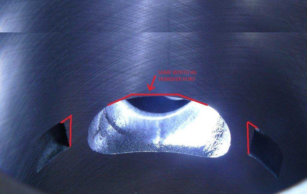 |
|
|
|
Post by sime66 on Feb 26, 2015 17:59:42 GMT
Thanks chaps – yes I’m up for it, and I do need help to have a chance of getting it right; I do appreciate it. I still have concerns about my skill and precision in measuring* and cutting too, but I think I said I wouldn’t mention that again. I’ll continue with tidying inside the exhaust, and opening the auxiliaries and losing the edges, for now though, the barrel is fitted for measuring. I’ve put the casings together with crank, piston and barrel on, and will do some measuring as my next job. Just for now, the Static Deck Height is practically zero (The crown is proud of the face of the barrel at TDC, and at the edge it’s about 0.4mm* below, with feeler gauges, if I had to commit to a dimension, but very hard to be exact because there is a chamfer on the inside edge of the bore). The piston (edge) goes below exhaust port by about 0.8mm* – that’s with just thin spacer fitted that came with kit (should I do it without?). I think that means that as I raise the barrel I’ll be able to tidy up the bottom of the exhaust port to get it level with piston at BDC? – As well as raising the top for correct timing? – That will give me a good chance to tidy both those edges up (and make a flat edge the same width as the transfer ports – top and bottom?). Then when I’ve got a new height for the top, I can raise the auxiliary ports to be exactly the same height, and lean them in as well like your mark-up – together with opening those channels inside the exhaust chamber too (I do have some long, thin diamond jobs, but I’m waiting for a smaller collet). The port opening chamfering and stuff is later – after I’ve got the ports right. I’ve tidied the head up properly now. I’ve also got the volumes to do: I’m waiting for a few bits to get on with a few of these jobs, but I’ll tackle it all as the stuff arrives. I’ve had a look at the match between the casings and barrel; they’re mostly Pretty close (photos tomorrow/weekend) – the main bit I noticed is the odd-shaped transfer ports and where that extra channel hits the blank casings. It looks like a big chunk could (should?) be taken out of barrel and casings to tidy that up. I have photos if you don’t know the bit I mean, but I’ll do photos, dimensions and sketches tomorrow or over the weekend, I've been busy today. I have a couple of questions to get me moving forwards: 1. I had to improvise some sleeves over the studs to tighten down the barrel. I’ve just got plastic ones for now, but if I have to torque precisely I’ll have to buy some tube and make some proper sleeves; what do you chaps use? Is torqueing precisely really needed or will tightened down do for this? – especially if I do it without the metal gasket? I’ll precisely pin down my Static Deck Height and exhaust port relative to TDC when I’ve got these sleeves and gasket right. 2. Am I concerned about the difference between piston crown an edge? I know we’ve talked about it before, but it makes a big difference as you can see from what I’ve said above at TDC the crown is over and the edge is under. It will be similar for BDC and the exhaust port. 3. When I get to raising the barrel, and assuming I’m needing in the region of 2.5mm to get the transfers close to 123-124º (from previous pages), do I use a 1.5mm and a 1mm like these?: www.sip-scootershop.com/main/base/Details.aspx?ProductNumber=19169600&_language=enwww.sip-scootershop.com/en/products/gasket+cylinder+base+th+15mm+_90780000I know those numbers aren’t fixed yet, and I know it would mean taking as much as I can off the barrel and head (which I think is less than 3mm available), but I’m trying to get an idea of what I’m doing and what timing it’s going to give me. I know it’s too early, and I’m going to ask some dumb questions before I get my head round the finished job, but I need a picture of the finished job to get an understanding of what I’m doing now. I’ll leave it there for a day or two, and post again when I’ve got some better facts and figures together, and see if any more posts help me progress. I’ll quickly post a few photos, just so that some of the stuff above makes more sense, but I’ll tidy it all up next time I get a chance at it.      |
|
|
|
Post by henri on Feb 26, 2015 21:21:42 GMT
right first off ,the diff between using plastic n steel spacers is prob sub .1mm , so no worrys , an ya measuring the edge not the crown ,thats where squish/the difference is ,
an i repeat my offer of old barrels to play with , pay postage an there yours , save me weighing em in at least , treat like real n learn the job on stuff it dont matter to scrap rather than ya new dr kit, a old 2 port barrel by hermes is bout 7 quid , a nother dr = 92 , i'm not the only one who's pointed out they wrecked 2-3 barrels learning the skills to do 1 right , please take em , you can weigh em in after or i'll pay postage back just to have a fiddle meself ,its a long time since i ported an i'd def practice on 1 before i went serious , private message me an we'll set it up, think on it , hours of fun dremmelling with no come-back ,a steep learning curve , thats the best kind , H
oh an got to say ,thanks sime i'm re-learnin stuff i'd carefully forgot , tuneittiss being a communicable disease , well if i'm goin down i reckon ive good company when i reach hell , we'll meet at the gate n storm the gaff , H
|
|
|
|
Post by sime66 on Feb 26, 2015 21:48:07 GMT
Thanks H, I've sent a PM. (There's a couple of you old hands getting the bug again, I think) - I've been to Hell; I'm barred! |
|
|
|
Post by vespasco on Feb 26, 2015 22:55:36 GMT
When trying to measure accurately, consistant readings are what youre looking for. Which means measuring a few times. Remember, when measuring the Deck Height, measure across the gudgeon pin so there is no play in the piston. If you had a chamfer on a set of calipers you could use them Ignore the chamfer on top of barrel, for measuring purposes, you need to measure from the actual flat gasket face. Measure the thickness of the gasket too, for your records. This will be your datum point so to speak. Like H says, its the edge of the piston/crown that you measure from/to. Its quite normal for the top of the crown to stick out over the top. Although, for your records, it may be handy to know the height of the dome and actual diameter of piston, (only to work out mathematical volumes) If your torque wrench says the nuts are holding 20Nm or however much it is, then thats how much it is, whether there are plastic, rubber or metal spacers being used. The rubber ones may need re torquing/ checking more often but for the sake of this project , what you are using will be accurate enough. I wasnt expecting the bottom of the exhaust to need any attention! But thats the difference between measuring components/using maths/theoretical values and measuring in-situ. Once you have definite figures for deck and port heights, you can work out exactly what you have now and as such, what you will want/need to do next to improve upon that. The method youre using is fine I also had, what i thought at first was a good idea...i was thinking of what cheap, everyday thing, could be used as a 'dummy' bearing for the purposes of installing/extracting the crank for measuring such things....something softer than ali - plastic! 62mm diameter ideally, easy to drill/sand....a skateboard wheel!!!!? Drill the inner to suit the crank, slice it down, voila!? Now all i need is a skateboard! If youre really worried about actually dremelling your new cylinder then Henris kind offer of a practice cylinder is a pretty good idea. Practice on that a few times, until you know how to prevent yourself slipping with the tool. Its difficult to explain but tips on using these tools, if you need any, relax yourself when youre actually grinding away but hold on to that tool with two hands, like its the last pint youll ever hold and you cant spill a drop. (Could be milk)! You need to control the tool, not the other way round. Then you're definately ready. |
|
|
|
Post by sime66 on Feb 27, 2015 9:42:32 GMT
Thanks for your post, vespasco; I’ll try to be brief because I’m holding off a proper post until I have some proper dims etc., to your post then: · Across the gudgeon pin – good point, had a quick look this morning and it does wobble a bit without the rings. – Noted. · Ignore the chamfer! – It’s a pain in the arse. I’ve done a detailed, well-lit, magnified, repeated (I even did a plasticine cast) inspection and measure of this bit, and I still could not confidently say what the vertical distance between the two points on my little diagram below is; I’m trying to measure over a chamfer, across a gap, with a feeler gauge at the angle of the crown; you chaps are talking confidently about +/- 0.1mm – I honestly do not think I’m able to be that accurate. I’m sticking with 0.7mm, but if one of you picked it up I bet you’d disagree. I don’t want to make a big issue about it, and I’m obviously always going to do my best, but I really do not feel I’m accurate to within the tolerances you chaps are talking about. I keep making the point, and it still concerns me. See photo and diagram:  (Since this photo, I’ve laid a steel rule on the face and slipped 0.65mm under it, so maybe I’m fairly close). · To use a torque wrench I’d have to get better sleeves, as it is these nuts are just tight enough not to crush the plastic sleeves. I’m not sure I’m crushing the base gasket, it does look like it is, but this is why I thought it might be better to measure the gasket and then do my measurements without it. – Or, as H said, it might not be too important. · The bottom of the exhaust is going to need even more attention when I raise the barrel. But that’s OK because I can lose that casting furrow and make a flat edge like the top will be too. I imagine the area of the exhaust port increasing is good, otherwise someone would have said something. (I know there’s nice calc sheets to play with, but I’m not there yet). · I had the benefit of old bearings still in the casings, so I just ground the inside of them slightly, and the crank went in smoothly (no play, but no force/tapping). If you want skateboard wheels, I think our ‘skate-punk’ would be your man. It would be good to have a better way of having this removable. I did try to think of all the measurements, mark-ups, photos etc., I wanted before I put the crank in, but I’m bound to want to pull it out once or twice before it goes in for good. · Talking of the man himself; I am most definitely taking the opportunity to have a practice, just as soon as H rolls out the barrel for me. I’ll be gripping my tool with both hands and relaxing (I won’t photograph that bit). All’s OK for the next stage of the plan, thanks for all the advice and stuff; I’m hoping next to be back with dimensions, sketches, calcs and photos, but I might be a few days to get it all together; it is after all a rugby weekend, and all this engine malarkey takes a backseat to actually riding the good scooter too! (Which I have this morning; it’s bright and sunny here, and she’s buzzing along just lovely……………) |
|
|
|
Post by henri on Feb 27, 2015 10:47:48 GMT
cutting skateboard wheels ?? thats heresy ,it'll be gullwing trucks at dawn me-laddy an no mistake , a gullwing between the eyes from 20 paces stings a bit i warn you , well ive never heard the like ,might have to go lie down for a bit now, an i was all ready to walk?? to the postbox with simes practice barrel , blame vespaco sime he started it ,
gaz's tip of shaving down a old bearing so it just slips into case an onto cranks is a better bet , i'm off for a calming walk in the sunshine ,an spose i'll drop ya parcel off ,so long as theres no more scurrilous talk of butchering precious relics , i'm off to steal a babys dummy n kick a stray dog to make myself happy agin ,an the day started so well ,shame on you both an i'll thank you if my outburst isnt mentioned again , never heard the like an other vague grumblings/mutterings as henri exits stage left ,H
|
|
|
|
Post by vespasco on Feb 27, 2015 18:50:45 GMT
Pmsl And i was gonna pm you the idea H! Thankfully the abuse was public so quite tame, so i think i got away with that one pretty lightly!? I guess you dont like the idea of a 'trike' skateboard either...oh well. I'll stick to Gaz's tip;) I just had too much time on my hands. Yeh, you got it, use a straight edge, steel rule, verniers on the gasket face If you got 0.65mm thats pretty damn accurate. Cylinders dont take too many torques anyway. Im sure your method is fine. Personally id use a gasket, if only to take up any uneven surface. Then again i have loads spare. and measure the thickness of the gasket! With reference to the exhaust port, or taking out the bottom....it does need it, but take into account this will enlarge the overall size of the exhaust port area...especially when youre taking some out of the top too...i dont really know if thats good or bad tbh but I know the exhaust is not right at the top of the list for its importance in tuning. Also re-measure to the top and bottom of the port from gasket face. I dont think your previous dimension was quite right (56.9mm?) Have a play with the port timing calculator, see what you have/will have before/after porting. Im hoping to be dialling in my carb and timing at the weekend. My jets have finally arrived! Yeh! |
|
|
|
Post by sime66 on Feb 27, 2015 19:42:40 GMT
As it happens I had best-bash at the other dims this evening, and I’ll bung these numbers in the Port timing calc tomorrow morning, and do a better sketch. My volume measuring stuff came today too, so I’ll have a bash at that too. With reference to the query over the 56.9mm, I bet you think I have a 60mm stroke – mine’s a 57mm. Here’s my rough dims – will tidy in the morning:  So, given the Static Deck Height of –0.65mm, and 57.00mm to bottom of exhaust port, and 57.76mm to BDC, I think my numbers came out OK, considering I’m measuring from on flat surface, to a rough-edged curve, which is sloping into the barrel too; I was quite happy to get to within 0.11mm; that’s OK I reckon. The exhaust port area thing is something I’ve got my eye on, and I’m sure it’ll all come out in the wash. If not I’ll have to do the reading I keep putting off. Bit of an aside – I put my flywheel on earlier to mark TDC while I had the head off. I had to cut the casings a bit where the head cowling fits, which I’d expected actually from reading before, but my question is, (and I know it’s a curly one), what’s a good weight for my flywheel? I ask because I bought an electric start one to maybe take the ring off if I decided to go lighter, but I ended up taking it off anyway because, as well as the trim I expected at the top, it was rubbing at the bottom, where I didn’t really want to have to grind it because it’s by one of the flywheel cover screws. The ring was 65grams, I haven’t weighed the flywheel yet, but it had 1.8 written on it; if so, it’s now 1.735kg. I suspect the lightened flywheel question might be a bit of a can of worms, but I’ve got to find out sometime…….. Enjoy the carb malarkey vespasco; it’s gonna be wet tomorrow; I’ll be out for a spin on Sunday morning. |
|
|
|
Post by henri on Feb 27, 2015 19:44:42 GMT
ive always fancied a 3 truck/6wheel board ,after seeing a guy in california beating porches/ferraris in downhill races, the trick was he never braked just hung on , an if ya think that abuse was tame you should of heard the ranting my garage witnessed today , my pops came out twice to say something ,just shook his head n said "keep it down,think of the neighbours" an went back in . did give me the inspiration/anger to go medieval on a montessa frame ,where talkin grinder/sander/wire wheel n stripper (paint not women ) ,but it did delay my droppin parcel at pick up point til after the noon van had been n gone , so if its a day later sime,blame vespaco,
an as for trikes type "smallframe drift trike" into youtube , its funny but mostly for when the guy trys n kick it over when in gear an nearly breaks his leg , hilarious , or is that just my warped sense? of humour, H
|
|
|
|
Post by henri on Feb 27, 2015 19:53:31 GMT
ya posted as i wrote , a lighter flywheel gives better revving response to throttle ,with a more uneven tickover as the downside , taking that into account as ya set it up i'd of reccomended lightening ya wheel for the tune your aiming for ,an 1.7/odd kg is about where you want to be ,any more weight loss is by machining an fin loss/cooling loss ,or machining fins right off an replacing with a bolt on plastic fan blades , not needed for a engine revving sub 10,000 , an really only reckoned for H2O cooled mental racer kits gettin into esoteric +30bhp territory there , H
|
|
|
|
Post by vespasco on Feb 27, 2015 20:22:14 GMT
Yeh sorry, that is ok. I was expecting something else for som reason. No worries. As for flywheel. I think by taking the ring off making just that little bit lighter, to give you a little faster acceleration off the mark. For you, you want the inertia of the flywheel to help keep the power on so not too light! I'm sure my notes read 300grm for the ring!? And i wouldnt trust whats written on it. My cheapo chinese scales only go upto 2kg and im sure my flywheel was more than that. But in answer to the question, whats a good weight..?? Only a theory but one answer would be - the same weight as the clutch!?! Another answer would be as Henri mentioned, lighter for high revvers Another answer - heavier for low compression motors I think without the ring, a stock flywheel is the cheapest and the best! Just like my rum Yah! *Edit Im glad i gave you some inspiration H. Anytime, just ask! Hahahaha |
|
|
|
Post by sime66 on Feb 27, 2015 21:27:41 GMT
I got the tracking for the barrel H, and it's in the system - something to play with next week/weekend. Well happy; thanks again.
Loads of stuff to do in the mean time - numbers is next job (that's a morning job for me though).
That 1.8 written on my flywheel is not the weight, the best I can do for now is to weigh myself with and without the flywheel, which is not very accurate, but it's more like 2.5kg - not light at all. I've had a quick look on SIP too:
Piaggio with E-ring = 2400g
LML no E-ring = 2350
SIP 'Touring' with E-ring = 1900g
SIP 'Touring' no E-ring = 1700g
Flywheel SERIE PRO HP4 = 1100g
There's loads of variation, but anyway I'm not in the light flywheel zone, nor do I want to be after a quick read; aside from balancing with clutch, which I'd read before, more weight for low-end, inertia, better tick-over etc., all as you chaps say.
I'll look into it more and weigh this properly later on, but for now I reckon I'm OK with this standard flywheel with ring removed.
Happy days.
|
|
|
|
Post by henri on Feb 27, 2015 23:05:46 GMT
bugger they picked up already ,damm . meant to make ya suffer for listening to "you know who's" heresy ,promise i'll try n let it go know , best for my blood pressure ,included the piston/rings/little end so you can mock up as if real , an remember , measure twice/cut once , then go back n fettle sum more til ya happy , thats what we all do, H
|
|
|
|
Post by sime66 on Feb 28, 2015 8:59:27 GMT
Measure twice, cut once, count fingers, if all still present then proceed to next job.... I’m in grave danger of getting myself in a muddle with me numbers, I’m still not confident with these porting calcs, but on first bash, it looks to me like 2mm packer(s), 1mm (or more, subject to checking squish and some clever chap’s input) off both the barrel and the head, which there is just enough meat for, and maybe an extra 0.25-0.5mm off the top of the exhaust would get me near to the targets of 124º Transfer, 174º Exhaust, (and the 125/55º Inlet with the case and crank mods too). As it is, form yesterday's measure, I reckon I have:Transfer 113.09º, Exhaust 164.68º, Blowdown 25.8º With 2mm Packer I reckon I’d have:Transfer 124.00º, Exhaust 172.99º, Blowdown 24.49º With 2mm Packer, and 0.25 extra on exhaust, I reckon I’d have:Transfer 124.00º, Exhaust 174.01º, Blowdown 25.01º ^^I do need to check that, and it would be great if anyone else could too - or more likely, correct it.^^ · For now I’ve taken my squish to be 2.8mm (static deck dimension + inner ring of head); I know I need to measure it, and to decide what the ideal is. · I’ve measured my head volume, and if anything get slightly higher than DR’s 23.69cc, but less than 24cc anyway (viscosity etc., makes precision tricky) · I will measure my gasket when I take the head off, but it’s just a thin metal job, so only about 0.1mm, and it will be a constant anyway, assuming I’ll still use it with (a) packer(s)? I’ll go back to this to check myself next chance I get, but I could really do with someone confirming or correcting me; there’s no rush – I know you’ve all got your own shed-stuff and real lives to get on with, but I just wanted to get the ball rolling before I get distracted by the weekend, even if my start point turns out to be nonsense. So here it is, now I can forget about it for a bit and get on…….. Here’s my working (measurements from yesterday’s sketch – not yet tidied):  Same result with my calc tables: Same result with my calc tables:
 2mm Packer (barrel/head trim TBC): 2mm Packer (barrel/head trim TBC):
 A bit extra off the top?: A bit extra off the top?:
 Head volume check: Head volume check:
 |
|
|
|
Post by henri on Feb 28, 2015 9:59:26 GMT
the slight discrepancy in head volume is probably the fluid bowing up slightly ,the more accurate way is by bolting a sheet of clear perspex across the head with a small hole in centre to fill by an allow air bubbles out.the results your getting are well accurate enough for your calcs , H
|
|
|
|
Post by vespasco on Feb 28, 2015 10:44:13 GMT
Just a quicky..... Youd need to know your gasket thickness before you start adding on or taking off 2mm of packers etc. With your 'x'mm thickness gasket (its likely to be 0.1or 0.2 mm) dont guess this after all your hard work measuring accurately. 0.2mm makes a lot of difference to your final figures! eg, if you gasket is 0.2mm thick: 0.68mm deck with 0.2mm base gasket = 164.68* With a 2mm packer it would be (0.68 DH less the 0.2mm gasket, plus 2.0mm packer = 2.48 DH) Ex = 172.29* Trns= 123.11* BD = 24.6mm If you can measure to +/-0.5mm with the equipment you have then youre doing pretty well Ideally, if you can, bolt the top end together including the head, (grease the perimeter of the piston/cylinder to seal it) then at TDC fill the combustion chamber up with measured oil to bottom of plug hole, then add the plug volume (normally about 1cc - 1.1cc) Or do like ze germans do/H suggested - plexi glass method and burette. |
|
|
|
Post by sime66 on Feb 28, 2015 12:02:48 GMT
This gasket business is becoming a bit of a confusion to me, so I reckon we need to make sure we’re all talking about the same thing:
Those measurements yesterday (Friday) were with the gasket that came with the kit. It’s just a normal flimsy metal base gasket – nothing special. It is not necessarily the gasket I’ll be using for the build. It is a thin metal gasket, I have just measured it now; it is 0.2mm thick, it has a ridge (seal?) that will not be crushed unless I torque the barrel down properly (does it crush?). Across the ridge is 0.4mm. My 0.65mm includes the base gasket - whatever it is; isn't that OK as long it remains constant, or is removed from 'before' and 'after'?
To me, to be more accurate, I would have to re-measure the barrel with either the gasket removed, or the head torqued down properly, with the base gasket I’m going to use for the final build, for which I’d also need better sleeves. My thinking was that it wasn’t essential to use the gasket thickness as long as it was applied the same way to the ‘before’ and ‘after’ dimensions, and if you want to remove it from the ‘after’ dimensions, then it would be better not to include it in the ‘before’ dimensions either – which seemed the best way to me because then the total packing needed would include the gasket. I reckon face-to-face we’d sort it out in a quick exchange – a bit of scribbling and pointing -, but I think we’re confusing each other, or I’m just not following something that’s obvious. Maybe quiet time in the morning will sort it out if I stop and have a proper think.
The gasket seems to be adding in an unknown, and the best solution to that would be to measure and calc with no gasket.
Also, before I look at your figures, which probably won’t be until tomorrow morning because I have distractions now, is your 0.68mm DH a misprint, or have I missed where you went from my 0.65 to 0.68mm?
Also, I’ll do the precise volume measuring if/when it becomes a critical factor; this morning’s exercise was to establish whether we’re in the right ball-park figures to the expected volume for the 1:8.5 (uncorrected) stated by D.R. For the volume measurements there has to be an acknowledgement of the inaccuracy of the method due to liquid viscosity, surface tension, bubbles, quality of syringes and cylinder graduation, etc – at some point just how accurate I need to be has to be weighed up against time, agro, cost of more precise kit for doing it more precisely if such precision is actually unnecessary. I do understand the procedure you suggest to get the volume in the barrel included, but again there’s talk about greater precision, then the grease in the piston edge seal and the gestimate for the plug as well as the above inaccuracies, so is all that effort really going to be more accurate? And what degree of accuracy is needed? – I do not want to be close to the limits of anything with what I do anyway, so I want a margin for error/safety in the volumes and ratios. I’ve got a 50ml measuring cylinder with 1ml graduations, the same graduations for a syringe, and 3ml pipettes in 0.5ml graduations – I don’t know how accurate any of those markings are, I don’t know how much sticks inside the head, barrel, plug, syringe, cylinder, I don’t know if any meniscuses make a critical difference without the plexiglass – this isn’t precision at this level of effort and cost of equipment; is greater precision necessary?
Maybe some of that will make sense, or clarify where I don’t follow your thinking with this base gasket.
In both cases I’ll do everything necessary to measure as accurately as is needed, when I understand the procedure, but I don’t want to be over-zealous with cost and effort of precision where is isn’t possible for me or necessary for the job; unfortunately, I don’t know where that demarcation is.
|
|
|
|
Post by henri on Feb 28, 2015 16:41:43 GMT
meniscuses , is that the word for liquids bowing up at top, knew there was one but couldnt remember enuff to stick it into google to find spelling,an your measuring stuff is probably marked with a +-tolerances of 5% , thats mostly because of the thickness of the markings ,with the pipettes being more accurately marked ,bout -+2% , to get better you'd have to buy high-end laboratory/chemist/pharmaceutical stuff . but as you asked/suspect what youve got is well accurate enough . its what i used when matching combustion chambers on multi cylinder engines,where the results are more critical because of balance factors .not a worry on a single cylinder tune . H
|
|


 Easy to make yourself but unfortunately only if you have access to a welder etc... Id suggest getting on your scooter one day and visiting your local engineering shop. Ask for an off cut of 10mm steel, 200mm x200mm is plenty big enough. Buy a coarse threaded HT nut and bolt, around 1/2" is ok. Prepare it all yourself, drill the holes if you can, then ask your local shop to weld the nut to the plate.. That should only cost a few £/the price of a drink if they're not grumpy ol' sods! You could also enquire about turning down your head/crank etc if you dedcided to go down that route.


 Plenty of work that can be done to that barrel to make it go better. Finishing the casting and chamfering all the ports seems like too much work for many of the factories to do.


