|
|
Post by sime66 on Jan 19, 2014 12:35:09 GMT
Anyone tried DC indicators, or want to think about it? This little planned improvement was delayed whilst I was messing around with my recent idling/cutting-out problem, but I seem to have done all I can with that one for now. I’m doing DC indicators and hazard lights, for three reasons: . Reduce load on regulator to improve other AC services, esp brighter headlight (alternative to playing with rear LEDs, Kru?) . Enable seemingly endless fault-finding on indicators without needing engine running. . As I’m replacing old switch anyway, to enable hazard lights even when engine is off / if I'm broken down. Needed these (£20):   Using this:  Made these changes to existing wiring:  To achieve this (Film - Working as intended with engine off): s1290.photobucket.com/user/sime6954/media/P1110893_zps21baf971.mp4.htmlHowever I have a slight problem, which I haven’t yet been able to solve, which is with the indicator dash warning light being wired up as it is on a Vespa (and not after switch as relay wiring diagram) it is permanently on. Looking at Vespa wiring diagram I can see why it’s happening (the supply is always live, and the switch is on-and-off as well as left-and-right), but I haven’t yet come up with an answer. It wouldn't normally happen because of the ignition switch. I’m going to persevere with it because the benefits are worthwhile, but for the moment I’ve had to put the AC flasher back on and think about it. Incidentally, I took a fused supply off battery because 'C' on Rectifier is intended for less than 2Amp - this is max. 4X21W @ 12v = 7Amp. Also, haven't put the new switch on yet - stopped for a head-scrath about dash warning lamp. |
|
|
|
Post by sbwnik on Jan 19, 2014 21:24:58 GMT
There is a thread on this over on Scooterboy-World.com Follow the link to the forum, hunt around the Vespa section, and there is a working one there. |
|
|
|
Post by sime66 on Jan 19, 2014 22:42:31 GMT
For anyone reading this, the SBW one is well worth looking at; it’s here: s4.zetaboards.com/ScooterboyWorld/topic/9496215/1/It doesn’t fully apply to my set-up though. I used some of the SBW info whilst mulling it over, and it does work; it’s just this dash warning light to sort out, which SBW (Tony) doesn’t mention. The SBW one uses the ignition-switched DC feed off regulator, which I haven’t got on an originally non-battery scooter. Anyway, I think that circuit is intended for low Amps, and I particularly didn’t want to use the regulator. I’m not sure that makes any difference; they might still have encountered this and solved it, or ignored it. My results - Using the battery to supply flasher relay I get:
. When indicators are switched ON (L or R) – Dash flashing correctly. Indicators flashing correctly. - As expected.
. When indicators are switched OFF (central) – Dash light constant ON. Indicators OFF. – Not as expected.Looking at the schematic, because the dash warning light comes off the red wire BEFORE the indicator switch, it is not switched off, but is permanently closed (on). I think that is the problem, and I haven’t yet worked it out, except it think the dash warning has to be after the switch, but that makes the wiring complicated, and the beauty of this is that it’s easily put back to standard. It’s a good idea, and it works, but although it seems trivial, the dash warning light is pretty important from a safety point of view and for MOT, so I need to work it out really before leaving it on DC. (I have not had the pleasure of the SBW induction, so I don’t post there, but it’s still a good source of info.) I'm still chewing it over. The other consideration is the type of relay. Looking at vespamaintenance, the (American?) P200 uses a different type of relay to solve it with an extra bit within the relay, and separate wire for the warning light: www.vespamaintenance.com/elec/signal/index.html |
|
|
|
Post by sime66 on Jan 20, 2014 8:55:32 GMT
Had a mate do the conversion on an LML, who didn’t have the problem. Although it’s an LML it shows why it works with that and a non-battery PX gives a problem; the circuit for the indicator warning light is after the switch, and there is a L & R warning light, so it works.  The problem with having one warning light, even after the switch, is that connecting both sides to it makes a circuit between the two sides. My part copy of my wiring diagram shows the offending red wire (removed, clouded) and a possible way of wiring both circuits up to one warning light with diodes (orange), but it’s getting messy and I don’t even know if it would work.  I’ve asked Beedspeed if they’ve encountered this before, and I'm waiting for their reply. It might end up proving more trouble than it’s worth, which would be a shame. |
|
|
|
Post by sbwnik on Jan 20, 2014 20:20:22 GMT
A mate is just ripping the wiring and components out of a US Spec DC model for me to use on the Cosa chop project.
That info is no use to you, I just thought I'd mention it.....
(As well as the unique indicator relay, it has a seven wire output stator!)
|
|
|
|
Post by joey on Jan 22, 2014 9:01:58 GMT
I carried out the conversion as posted on SBW and my problem is that as soon as ign key is turned the relay starts clicking and warning light flashes?  Any ideas? |
|
|
|
Post by sime66 on Jan 22, 2014 10:51:01 GMT
Yes Joey, I know why, but I can’t explain why SBW (Tony) didn’t have the same problem. I can explain the problem as I understand it, but you need to read thoroughly to follow it. I can’t quite yet give the solution either though. I checked the link SBWT had for his relay, and it’s for LEDs and from Hong Kong, so I avoided it. (Might have been a mistake though because his worked). I bought a WRE06, which is DC (or AC) 12v for 4x21W. This does not need a direct connection to Ground because X & P both go to ground. (I do not know whether SBWT was right or not to have one). The connections for the WRE06 are: L = +12V Dc (or AC) X = To indicators P = Pilot – to indicator warning light. I tried wiring it up as SBWT had initially and the indicators all worked, but the pilot light stayed on when not indicating, so I checked and found that L,X,P wired as above is correct. To make a dedicated warning circuit, instead of joining the Red & White wires at the relay (as SBWT did) I joined them at the horncover terminal block. Which made the big White wire common for front and back, to the switch, which is off, left & right. That all works and leaves the Red wire for the indicator warning circuit., which you can see on my schematic now goes straight from relay to speedo warning light, via horncover conn block. I think the problem with this circuit is it is live – in your case, when you switch the ignition on; and in my case, live at all times because I do not have a switched DC via the ignition on an originally non-battery scooter. Later scooters (I used my mates LML as an example before) overcome this by having two (left & right) warning lights coming off the indicator circuits AFTER the switch. Our problem is taking the warning light of BEFORE the switch because it is live. You can’t take two wires off after the switch to a single warning light because it makes a circuit with the other side of the scooter. I need to have another go on the weekend to be certain that a single warning light BEFORE the switch won’t work, or if it does I’ll post the solution. I currently have the indicators working correctly and the warning circuit disconnected, which is not OK as a permanent situation, nor will it pass an MOT. If you make progress please share it. I’ll post the wiring diagram of my set up now, which shows how I have the relay wired and the horncover modification I did to free-up the Red wire. (The short Orange loop).  |
|
|
|
Post by sime66 on Jan 25, 2014 12:10:56 GMT
Finally the DC services are all working.These LEDs are only a temporary solution because they’re a bit flimsy, but a pilot light for each side AFTER the switch, like an LML does it, was the only way I could see it working. There are spare connections at the back of the front indicators. I’ve also got my fog/spot/driving light and horn off the battery, so it all works when the engine is not running. By that I mean when I am broken down, which has been rather more frequently than I’d like recently! There is also an LED work lamp that recharges off the cigarette socket, so I can work at the rear in the dark. After some messing about with the reg/rec the battery is charging properly now too. I know this thread didn’t generate a lot of interest, but to tidy it up here’s my final wiring diagram and a bit of film with it all working. I’ll be getting a couple of waterproof green panel lights for the top of the toolbox when I find a suitable pair at a sensible price. FILMs1290.photobucket.com/user/sime6954/media/P1110899_zpsed299218.mp4.htmlSCHEMATIC The other matter with misfiring/cutting out has been sorted, I think with the new carb, and I'm currently running with no problems that I'm aware of. How long for I cannot say. Bring on the Spring; I'm ready................ 
|
|
|
|
Post by sharpcroft on Apr 19, 2016 14:14:32 GMT
Hello mate
I know this subject has been dead for a while but did you ever get to the bottom of this?
Im trying to do a similar thing on a T5 classic that i have fitted a 5 pin regulator and battery to.
What i have done is replace the 3 pin flasher relay with a 2 pin jobby (with a built in buzzer), joined the front and rear indicator circuits, removed the AC feed to the relay and replaced with a live direct from the new battery. My symptoms are that the indicators function correctly when selecting left or right but when in the off position the flasher relay still clicks in and out ( i know this because the inbuilt buzzer is buzzing on and off) but without the indicators flashing?
Did you ever get a working "work around" for fitting DC indies on a scooter not designed to have a battery?
Cheers
Sharpcroft
|
|
|
|
Post by sime66 on Apr 19, 2016 15:02:26 GMT
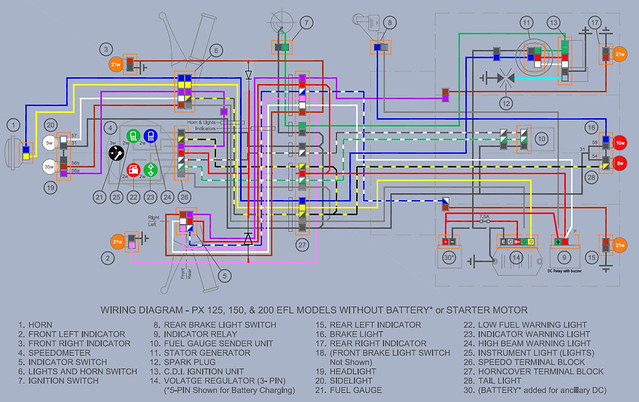
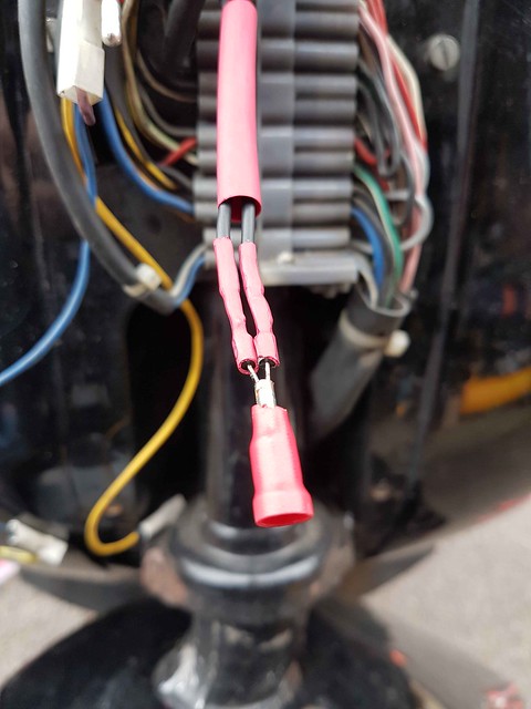
Getting the DC indicators to work was easy once I had the correct flasher relay (see bottom), getting the single idiot light to work for both sides of indicator was the problem. I did suss it out, and it’s working properly now; the trick was isolating the old idiot light circuit, and making a new one with a tail from each front indicator, with diodes in each tail to stop the cross-circuiting between left and right. I also still found a potential ‘leak’ in the front indicator earth wires, so ended up putting a diode in those too. If you look at the new wiring diagram below, I’ve isolated the red from the relay (but left it in-situ in case I ever want to go back to AC); the white now serves front and rear, and I’ve taken new tails from the back of the front indicators for the idiot light (Orange on schematic): 
This diagram shows a toolbox buzzer, but I soon dumped that malarkey!
Here’s an image of the diodes and tails, and the little idiot light circuit I made, which just plugs into the front indicators’ spare spades, and pokes through to behind the horncover, where it connects back into the old idiot light circuit:


There’s another thread of mine on it somewhere, I’ll look for it later, but it probably explains it better because I wrote it when it was fresh in my mind, rather than me trying to remember the logic of what I ended up doing a couple of years ago.
See if any of that makes sense. Feel free to ask any questions; I might remember better later after I’ve had a chance to refresh my memory.
They were 1N4005 600V 1A Diodes, from pw928gts on Ebay – he was very helpful; 25 of them for £2.50, here:
www.ebay.co.uk/itm/1N4005-600V-1A-Diode-Lot-of-25-/170859018948?hash=item27c7fdbac4:m:mplpZVxdsgs4ucAHjdsQXAw
I have just replaced my flasher relay; this one was a straight swap for the old, dead one, and woked correctly, immediately, with no tweaking:
www.ebay.co.uk/itm/171926479944?_trksid=p2057872.m2749.l2649&ssPageName=STRK%3AMEBIDX%3AIT
|
|
|
|
Post by sharpcroft on Apr 19, 2016 18:07:33 GMT
Thats a great help, many thanks.
That flasher relay looks like what i have except mine has a built in buzzer, not as loud as the butty box type but audible enough to hear with a lid on.
I've put the indicators back to standard for now (im off out on a ride in a minute) but will deffo give your wiring mod a go as DC indicators on my newer battery PX and my old (now sold) LML were brilliant, bright and reliable, it also had the side effect of making the head and tail lamp brighter and steadier.
One strange thing i did find was that before i fitted the battery but with the 5 pin regulator fitted, i took the DC feed from the B+ terminal on the regulator to the B (live in) on the 2 pin indicator relay/buzzer and with the engine running everything seemed to work fine as far as the turn signals go, cant vouch for the tell-tale as i cant recall checking it, it was only when the battery was introduced to the circuit that the indicator relay started clicking when the indies were off? I wonder if had something to do with the DC earth from the battery to the frame that was connected in the same place as the AC "earth" from the regulator?
Cheers for all the pointers
Sharpcroft
|
|
|
|
Post by sime66 on Apr 19, 2016 19:19:48 GMT
Yes, much better off the DC for sure, I’ve got the hazard switch too, and it’s all easier to troubleshoot without the engine running as well. I think when you do the DC indicator mod the idiot light problem will surface and you’ll see why most of my earlier reply was on that bit; you won’t have had the same problem on LML because it has a left and right idiot light, and they’re wired differently. Don’t underestimate the problem of running both sides with one idiot light off a DC relay off a permanently connected battery; although you’ve got the solution here now, which I didn’t have when I encountered it, so it should be easy for you. Some of the others had relays clicking, and put it down to a constant DC circuit through the idiot light (because they were using the old wiring). Here’s the thread I was thinking about earlier, and 3rd & 4th July the chaps started banging on about it, as they had in this thread in January too, but I’d fixed mine by then and had given up trying to explain that their problem was because the existing idiot light wire was before the switch – you’re making a circuit direct from battery to relay to idiot light to earth. vespa.proboards.com/thread/4121/indicator-warning-light-buzzer-requirementsI tried to explain that if you used the old wiring, which takes the idiot light connection off before the switch, you’ll make a DC circuit through the idiot light, but if you do as I did (and LML does), which is take the circuit from the indicators after the switch, then you don’t have a circuit unless indicators are switched on – it’s all coming back to me slowly; I suspect that might be the cause of your clicking. Take a look at a LML wiring diagram and see it’s what they do. Do what I did; isolate the old idiot light wiring and make a new ‘Y’ piece coming from front indicators with diodes and connect back in behind horncover - it works! |
|
|
|
Post by sharpcroft on Apr 20, 2016 14:54:14 GMT
Just a thought, would just fitting an LED idiot light do the same as fitting all the diodes and allow the use of the original wiring?
Sharpcroft
|
|
|
|
Post by sime66 on Apr 20, 2016 16:23:35 GMT
Maybe it will, but I see the problems as explained above; it might be best for you to just try it, see the problems for yourself, and work out your solutions – then share them with us - let us know how you get on; I’ll be interested to see.
|
|
|
|
Post by henri on Apr 20, 2016 16:29:15 GMT
i tried using leds on a bike i fitted a koso speedo n idiot light nacelle too ,as it was wired with 1 indie light like vespas . the problem was caused by led indies being fitted an the bleed back through idiot light was enuff for both indicaters to illuminate at once no matter which side was switched too. i couldnt get it to work tho an never sorted what the hiccup was . if on the dc side led's should work , but on vespas ac side unless wired with a resistor in the circuit the voltage spikes will kill them quickly . H
|
|
|
|
Post by sharpcroft on Apr 20, 2016 16:30:41 GMT
I,ve ordered the diodes, i've got a selection of 2 prong flasher units, all dc, some 10w max, some 60w max and with and without buzzers so i'll have a play when the diodes arrive.
Thanks again
Sharpcroft
|
|
|
|
Post by sharpcroft on Apr 20, 2016 16:34:17 GMT
i tried using leds on a bike i fitted a koso speedo n idiot light nacelle too ,as it was wired with 1 indie light like vespas . the problem was caused by led indies being fitted an the bleed back through idiot light was enuff for both indicaters to illuminate at once no matter which side was switched too. i couldnt get it to work tho an never sorted what the hiccup was . if on the dc side led's should work , but on vespas ac side unless wired with a resistor in the circuit the voltage spikes will kill them quickly . H Im using LED's in the tail and brake and have used LED's in the indicators on various LML's and PX's, all on AC and never had a problem as long as you buy 1/2 way decent LED's and not 50p a shot Chinese cr*p Sharpcroft |
|
|
|
Post by sime66 on Apr 20, 2016 16:36:51 GMT
if your plan doesn't work you have a working solution above, let us know how it goes
|
|
|
|
Post by sharpcroft on May 25, 2016 16:22:34 GMT
OK finally got round to doing this today, kept red wire connected at the relay and joined it to the other indicator wire, cut the red "idiot light" wire at the horn cast connector and put a male / female bullet connector on the cut ends incase i ant to go back to AC indicators, soldered in the diodes and connected all up, strange thing is it all functions great, as in no clicking relay etc when ignition is on and indicators are off but what i do get is a faint glow from the "idiot light" constantly when the indicators are off or on but the faint glow turns into the correct flash when the indicators are switched on, not sure why im getting the faint glow or if it gonna cause a problem?
Any idea?
Cheers
Sharpcroft
|
|
|
|
Post by henri on May 25, 2016 19:14:05 GMT
could be as the idiot lights on a common earth with other speedo lights the dim glow is "bleed-back" from the ac side . or have you tried swapping in another relay as it might be a faulty relay bleeding thru enuff voltage to glow idiot lights but not indies themselves . H
|
|
|
|
Post by sharpcroft on May 25, 2016 19:48:58 GMT
|
|
|
|
Post by sharpcroft on May 25, 2016 19:55:00 GMT
could be as the idiot lights on a common earth with other speedo lights the dim glow is "bleed-back" from the ac side . or have you tried swapping in another relay as it might be a faulty relay bleeding thru enuff voltage to glow idiot lights but not indies themselves . H It is a low wattage relay only rated for 10w as i was aiming to swap out the bulbs for LED's but managed to buy the wrong bloody ones lol, i have another few relays al 2 pin rated higher (60w) with and without buzzers so will give them a try when i get another 5 minutes. Failing that i think i can live with it as its not causing a problem as long as its not seen as an MOT failure? it does flash and i also have the beeper its just that during the "off cycle" of the flash its not off its just dim so the idiot like act so: Indicators off: idiot light dim (dependant on engine revs) Indicators on: idiot light bright-dim-bright-dim etc Cheers for the helo (and the wiring diagram) Any chance of a copy of the ones you've got with layers? Sharpcroft |
|
|
|
Post by charles on Jul 13, 2019 5:49:46 GMT
Hi guys, Realising this is an old thread, but did anyone find a definitive solution to the get the idiot flasher light to work? Just replaced the square indicators on my 2001 battery PX for smaller LEDs via new DC circuit and had the same problem... until I found a unusual, but natty solution. Idiot light work perfectly. Anyone interested/listening out there? |
|
|
|
Post by scooterg on Jul 13, 2019 12:18:11 GMT
We’re always listening,,just in the background
|
|
|
|
Post by mijapxman on Jul 13, 2019 15:35:28 GMT
We're all here to learn. Fire away 😉.
Mij☺
|
|