|
|
Post by vespasco on Nov 20, 2014 0:57:00 GMT
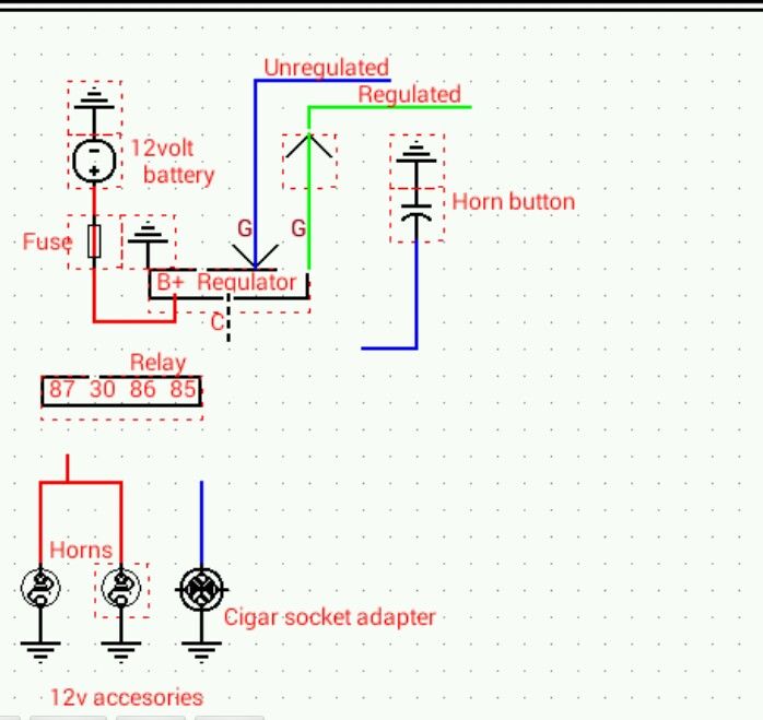
Heres what i have....
I just need some help joining up the dots!!
In order for the horns to work by pressing the horn button,
can someone tell me what should go where? Please
Ive no idea how these relays work or why i would need one?
Forget the A/C circuit.
Would i need a switch or something for the socket adapter too?
 [/a]1[/font]
|
|
|
|
Post by sime66 on Nov 20, 2014 8:59:19 GMT
I spent a lot of time on this 18 months ago; you’ll find my efforts here: vespa.proboards.com/thread/3476/motobatt-any-good(Scroll down past battery selection stuff) I ended up with a tidy little fuse/relay board, which fits in my toolbox, up out of the way. I have relays for just DC horn and Camping/Fog Spot; the 12v socket(s) have no switch, unless you want to, but are fused. I reckon you could have your horn switch the other side of the relay (85 to ground), as you show, it would be the same, but I had mine slightly differently, and I’m showing you what I did (86). It has always all worked perfectly. The relay is to save the switch (on 85/86 trigger circuit) from the full load (30/87 circuit). On my horn now I have a foot button switch, which is rated to be OK for horn load, but I’ve left the relay in because I’m going to change the switch next year to one on my right hand grip where the AC one is. I decided to forget about the ‘C’ on the rectifier; it has a small load capacity, which I can’t spend time looking for now (It’s in the wordage of the thread linked to above somewhere), but it seemed insufficient for anything useful for me; all my stuff comes off the battery, which is charged, fused off the ‘B+’ on the rectifier. So, this for your's: My little board: My little board: I didn’t bother with the fuses on the trigger circuits, it should have them though, just never got round to it and never had a problem (yet). (If you do follow that old thread above, Note: The early schematics were later developed to omit the Earth return or any use of 'C'. The wiring around the reg/rec has now changed for my DC indicators, so is out of date too.) |
|
|
|
Post by henri on Nov 20, 2014 9:22:19 GMT
tidy lookin board there , H
|
|
|
|
Post by vespasco on Nov 20, 2014 10:39:12 GMT
Thanks sime, that looks pretty good.
I will have another read through but one query popped up in my head....
The horn button connects to earth for it to work.... If i wired it as suggested would it still be work?
|
|
|
|
Post by sime66 on Nov 20, 2014 10:56:55 GMT
Either way works; the switch is just completing the 85/86 circuit from live to earth, which triggers the 30/87 circuit. I’ve had it both ways whilst playing with mine; it makes no difference which side of the relay the switch is. The switch after the relay is fine too. (It doesn't even matter which is 85 or 86; it's just this:)  |
|
|
|
Post by vespasco on Nov 20, 2014 11:32:49 GMT
Now it all makes sense!!
Ive been going through my notes of late.... I found conflicting wiring diagrams!! Hence the questions.
Now i believe i understand it much better!
Thanks again.
|
|
|
|
Post by sime66 on Nov 20, 2014 11:56:50 GMT
I had a quick scan through the Net to check myself; most schematics I found quickly show what I have above.
Thinking it through, if you put the switch after the relay, you have the relay on the live-side of the switch, which might matter.
Mines as above (switch before relay), but I still reckon you'll be OK if it's easier for you after the relay, if you're happy with that proviso.
|
|
|
|
Post by vespasco on Nov 20, 2014 12:11:38 GMT
So next question..... Take a look at the battery feed, in and out.... Would both these circuits work equally well? The one on left would be ideal i think? But is the diagram on right possible?! I should have paid more attention in Physics classes!! 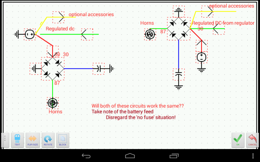 |
|
|
|
Post by sime66 on Nov 20, 2014 12:48:13 GMT
I think your diagrams have clouded the matter somewhat, especially the right-hand one. You’ve shown a bridge rectifier with three earths and one live; you need to think of the 4-pin relay as two separate circuits as the mini relay diagram above, each with a +feed and an earth, in your case they are the main (Horn) circuit (30/87) and trigger (Switch) circuit (85/86). Each of these flows from battery to earth, the current in the trigger circuit closes the circuit in the main (Horn) circuit, (which then plays the natty tune of your choice - or a good, loud blast!!).  The two positives are: The two positives are:Main – 30 (From battery, fused) Trigger – 86 (From battery, fused, preferably switched*) The two to earths are:Main – 87 (Via Horns) Trigger – 85 (possibly switched*) I think you should get that bit right in your diagrams before showing optional accessories on either, which should be from the battery and fused as my first schematic. I think also that you shouldn’t have regulator connecting to relay, which your right-hand diagram shows. I think schematically they do the same job, you just don't want all those connections at the relay. Your left-hand diagram would be OK if you showed the left connection as a fused positive from battery (86), not an earth. Your right-hand diagram is nasty!  Your ancillaries should be from battery – not lots of connections on one relay. I hope that helps; I'm trying to answer before you edit your question, and I'm trying not to dwell too much on what was going on with the right-hand diagram because it looks dodgy to me. . . . . Edit - addition:This might help, it's from when I was working it out for my board - I think it helps to keep the relay wiring thinking away from the battery/rectifier wiring. (The two Right-hand side feeds to fuses are from battery - the battery is up the back with the reg/rec; this lot is the board in the toolbox up the pointy end)  |
|
|
|
Post by henri on Nov 20, 2014 14:59:34 GMT
i'm with sime ,that righthand piccys a bad way to go , as he says on the leftie (like meself) get rid of rectum-fryer piccy n put a relay in an fuses an its good to go,
earlier sime wondered bout which side of relay to put switches , it doesnt make any diff wether its a switched live or switched earth ,the relay cant tell an will still work , its easier to use a switched earth as thats how the horn switch is already wired ,thats if your still going to use the bar end switch to trigger old an new horns together or just new ones . H
|
|
|
|
Post by henri on Nov 20, 2014 15:02:16 GMT
i'm with sime ,that righthand piccys a bad way to go , as he says on the leftie (like meself) get rid of rectum-fryer piccy n put a relay in an fuses an its good to go,
earlier sime wondered bout which side of relay to put switches , it doesnt make any diff wether its a switched live or switched earth ,the relay cant tell an will still work , its easier to use a switched earth as thats how the horn switch is already wired ,thats if your still going to use the bar end switch to trigger old an new horns together or just new ones . H
oh ,an when putting a relay into the piccy change lefthand earth sign to + feed ,
|
|
|
|
Post by vespasco on Nov 20, 2014 18:51:01 GMT
I think ive got it , by jove. Thanks to you guys. Does this look right? Looks good to me (finally)!!  |
|
|
|
Post by sime66 on Nov 20, 2014 19:01:32 GMT
Nearly, BUT86 has to be from battery, not to earth; 86/85 is the trigger circuit from battery to earth. (You still show both connecting to earth). Extra notes: You also need fuses on the green and yellow, but I think you know that bit.  You can move the horn button to 85 if you want to. |
|
|
|
Post by vespasco on Nov 20, 2014 20:07:50 GMT
Yes!!!! The horn button threw me a little to start with but i can see clearly now  Is the one fuse sufficient for both of these feeds? Ideally there should be 2 i guess but Im hoping to keep things to a bare minimum. 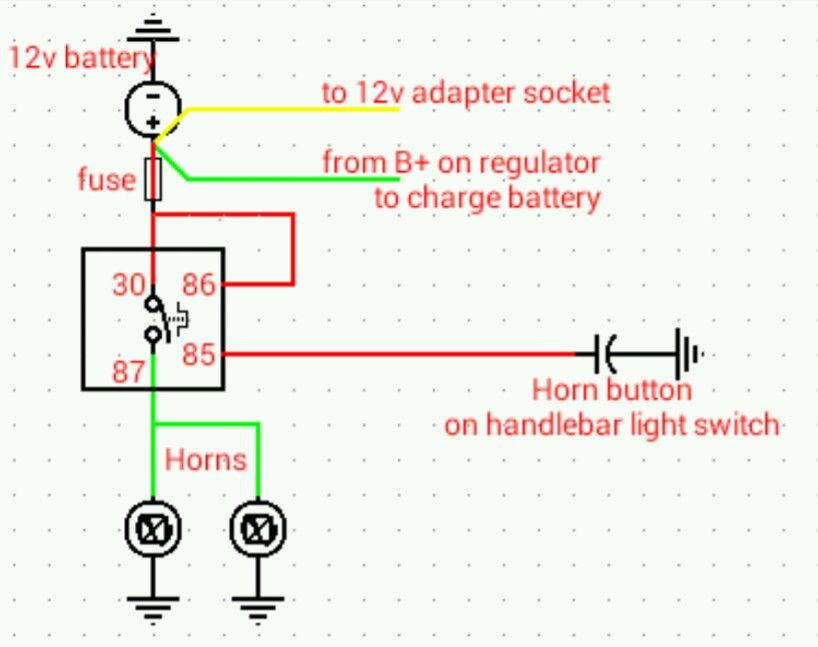 |
|
|
|
Post by sime66 on Nov 20, 2014 20:28:12 GMT
I have one fuse, like you show. I think you should have a small fuse on the trigger circuit as well, but I didn’t, and as I said above it hasn’t mattered (yet). This business of using the horn button on the light switch rings alarm bells though; if it is the same sort of switch as on my PX (I don’t have your Rally wiring diagram, or the inclination to go looking for it right now – because I’m in the middle of changing my graphics card on my computer), then that horn button is not as simple as it seems. If you know what you’re doing there, then go ahead and ignore my caution, but I tried using the old AC horn button for my DC trigger, and gave up after limited success and too many nightmares. The link to my investigation and progress then is here: vespa.proboards.com/thread/3547/dc-horn-relay-trigger-circuitThe problem being that in my case, my PX, that switch is on unregulated AC, and its wiring comes from stator to regulator, via the horn and switch. Bypassing it, or reusing it proved tricky. I won’t say it ended in tears, but it got too complicated to bother with, which is why I ended up with the foot button switch. Your situation may be different, anyway tonight I’m under my desk trying to fix my computer……………….Probably got an hour in the morning if it’s still working then and not been chucked out the window. |
|
|
|
Post by henri on Nov 20, 2014 20:58:42 GMT
the relay is placed in shortest line from battery to horn with larger 10amp type wire or more if its a mighty affair ,the trigger circuit is run out of 5 amp thinner wire so its easier to run up to button ,i was bout to say like ya lectric start relay then membered " rally" ,but thats the point of a relay so ya dont have to run heavy gauge cable up to a switch n put a resistance in the circuit coz of extra length,
when talking of using existing horn button i'd presumed youd swapped to 12volts already an its a push to make type , not a earlier push to break ,if so a diode in the line should allow you to run a ac horn an dc 1 on same switch , but its simpler to swap to a dc type horn ,you'll have to hunt out a dc type one or drill a px 1 n rob the chrome cover from ya ac 1 by drillin rivets ,H
|
|
|
|
Post by vespasco on Nov 20, 2014 21:10:14 GMT
Thanks sime. And h. That helped a lot. I got there in the end ! I see the separate circuits (and raise ya a 4 way resistor)! I was chuffed enuff that i worked out the symbol for a relay, haha! I have to put this practice tho' Im 99% confident that my horn button is totally separate from the ac circuit on the switch. Ain't gonna be no PCB on my watch godammit! Keep your notes well stashed henri, they'll lead to all kinds of shannigans if they come into contact with sunlight. I made the loom myself, which is fine, as i had definitive diagrams to work by but adding a dc circuit and a relay .. Well... now i know Thanks chaps |
|
|
|
Post by vespasco on Nov 20, 2014 21:18:59 GMT
Cheers henri! I missed your reply when i wws typing mine... I can picture how they work in my head now. And what they achieve. Im not going to be using the stock horn at all. Its just there for show.. and the rally horns are the larger 86mm? , more expensive ones |
|


