L12ARD
1st Class Ticket

Posts: 82 
|
Post by L12ARD on Apr 13, 2017 15:35:24 GMT
T5 Millennium (non elec start)
Running sweet as always on way to work ... Then a gremlin got on-board and the electrics went haywire ...
Suddenly No headlight/sidelight or main beam , No rear light except brake light working... Also indicators not working unless applying brake then they work ...
Main beam/Headlight show up as on on the clocks/speedo face , but the indicator light on the clocks stays on not flashing as normal, unless the brake is applied then they flash on and off the clocks as normal ...
If that makes any sense , any advice where to start ?
Thanks in advance for taking the time to read this post ...
Steve |
|
|
|
Post by doulsy on Apr 13, 2017 22:00:30 GMT
some wires might be touching, if wires are touching then the stator wont put out, get a voltage meter
|
|
|
|
Post by henri on Apr 14, 2017 7:11:56 GMT
1st check connector block on engine .
2nd connections on reg box
then work forwards to headset end ,brake light switch ,connector block behind horncast then switch gear .
to me sounds like a bad connection somewhere ,also swapping reg box for a known good one is a usual 1st guess,they fail in many weird ways .H
|
|
L12ARD
1st Class Ticket
Posts: 82
|
Post by L12ARD on Apr 14, 2017 8:29:27 GMT
Cheers guys , given me something to look into over long weekend , want it right for Bangers n Mash next weekend ...
Steve
|
|
|
|
Post by sime66 on Apr 14, 2017 12:05:09 GMT
Hi Steve, I think you’d benefit from thinking about your wiring diagram alongside the symptoms you wrote, because what you wrote makes quite a lot of sense – that doesn’t mean there’s a single simple answer, but if you think it through………. 1) No headlight, sidelight or main beam – these are on the same live from regulator, via horncover connblock to switch, and then to lamp. 2) No rear light except brake light working – they’re on different circuits; the rear light comes from same live as headlight (but comes back out of switch differently, but brake light is on a different live from regulator (via branch to indicators and brake light switch). 3) Indicators not working unless applying brake light (these are both on same live circuit from regulator). 4) Main beam/headlight show up as on on the speedo (although on same live from regulator as headlamp, they branch at horncover connblock – this one in particular narrows down the headlight problem). 5) The indicator light on the clock stays on (that’s bulbs or flasher relay probably, but in conjunction with previous (3), suggests an inadequate AC from regulator to trigger relay, or problem with bulbs/flasher). In addition, obviously, you need to check stator output, regulator input and output, shorts and bad earths, but there is some logic to your symptoms, which might be easier to find if you compare your symptoms with the actual circuits. If there is one single source of a sudden problem, the only common parts to all symptoms are the wiring from stator to regulator and the stator and regulator themselves, otherwise there is more than one problem, which is likely given some other circuits are ok (eg brake light) . I’m not going to hunt down a T5 Millennium-specific wiring diagram, but if it’s the same as a non-battery PX, it’s something like this (excuse scribbled sketch, from memory, not gospel; I suggest you find your correct wiring diagram):  |
|
L12ARD
1st Class Ticket
Posts: 82
|
Post by L12ARD on Apr 15, 2017 6:34:21 GMT
Wow ... thanks for taking the time to ponder on the faults and post that Sime ..Top Lad
Steve
|
|
|
|
Post by sime66 on Apr 16, 2017 9:03:38 GMT
I’m posting my reply to your PM here, so others see it as well; I think you’d be better off with their experience too.
You’ve found that head, side and tail lights are all blown, (and you still have that indicator problem).
I did suspect the regulator because it’s common to all the problems, but I’m only thinking logically with the wiring diagram, rather than with the long experience of some of the others on this forum. Stuff that I have to think through, might be obvious to someone who’s been repairing loads of different scoots for years, and seen it before.
I’d be thinking that the regulator gave out a dying surge to blow the bulbs and is now not giving out enough to trigger the indicator relay (or maybe it killed that too), and didn't blow the brake light because that circuit wasn't live at the time of the surge. I think that possibility might explain everything you said originally; I would say it's looking like regulator.
Checking your stator output first (blue on mine), and then regulator input & output with a multimeter, (check its earth too), or just swapping the regulator with a new or known-to-be-good spare would be the next step, and that’s before trying new bulbs otherwise you might blow them again.
I hate troubleshooting my own electrics, so trying to do someone else’s over the Internet is very difficult, I know it’s a crappy job, but you just have to think it through and systematically narrow down the possibilities until you find it. In this case starting with the regulator seems the best approach.
I’ll have a look back on here later to see if you’ve got anywhere, but think you’d be better posting here, for everyone who's about over the holiday to chip in, than PMs.
|
|
L12ARD
1st Class Ticket
Posts: 82
|
Post by L12ARD on Apr 16, 2017 13:18:35 GMT
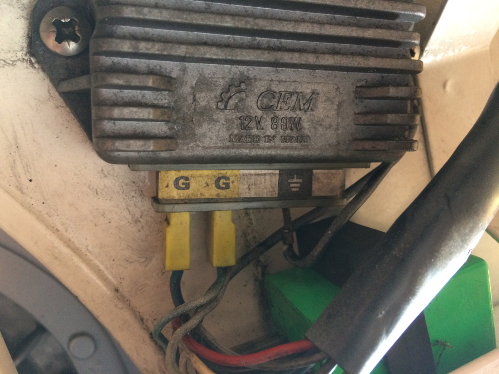 Not great or even competent with electrics but hey ho , owt to save garage labour charges... Took the 3 pin Regulator(pictured above) off the scoot to test it with the multi meter on Diode mode ... Two G pins l/h/s and the ground/earth r/h/s Multi meter only pics up a circuit (0.01) between the two G pins . nothing between the Ground and either of the G pins This mean anything or do I need to dig further afield .. Steve |
|
L12ARD
1st Class Ticket
Posts: 82
|
Post by L12ARD on Apr 16, 2017 13:32:19 GMT
P.S
I don't suppose its related but only other thing I've changed recently ,is when I serviced it a few weeks ago and replaced the plug , HT lead and plug cap ...
(Plug cap used to be the one that keeps the screw nipple on the sparkplug , one I've changed too is the cap that requires the screw on nipple removed)
Steve
|
|
|
|
Post by sime66 on Apr 16, 2017 14:59:44 GMT
No mate, I said check your stator output first (blue on mine), and then regulator input & output with a multimeter, (check its earth too).
I’ll break that down into chunks; we are talking about 12v AC; so set you multimeter to AC (~):
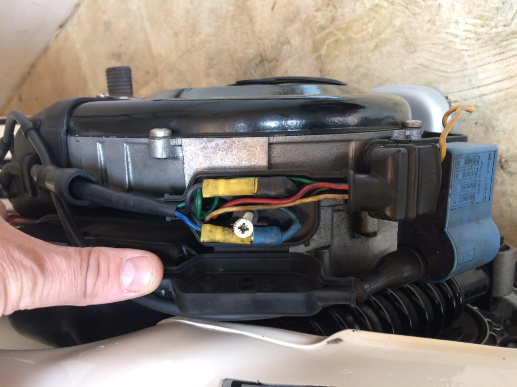
1) You can’t be certain that the regulator is duff unless you’re already sure that the stator AC (‘lighting’) coils are working, so you should check that first. To do this you have to take the top off the black box on top of the flywheel casing, unplug the multiplug that has the black and blue wires to the loom (the ones that don’t go to CDI), stick the +ve multimeter probe into the blue spade connector and hold the other one to ground (the frame) you should see decent AC voltage (~) at tickover, and you should see it rise as you rev.
2) To be sure there are no shorts, I would also reconnect the conn block and check that circuit both sides if it passes through your lightswitch (you will have followed previous advice and found your wiring diagram to check that, before PM’ing me on Easter Sunday morning, I hope), and I would also check it just before it connects to the regulator (that’s the single (blue?) wire going into the regulator); I think the left-hand one on your photo. – These should all be the same if the stator is good and it’s getting to regulator without shorts.
3) When you’ve established whether full UNREGULATED AC is getting to regulator, you then need to plug that wire back in to check the regulator output to do this you need to unplug the joined (grey and green) wires that go to loom and to the indicator relay, poke the +ve probe in there, and touch the –ve one to ground (frame). This should be giving you 12V AC regardless of revs – that’s what it does. If stator is good and that isn’t 12v AC, that’s your problem (or at least the first part of it).
4) While you’re at the regulator, check the black wire from it (the right-hand one on your photo) is intact and connected to ground under one of the regulator fixing screws.
If that’s too complicated, and I understand lots of people don’t like electrics, then just check your stator and try a new regulator, or even don’t bother with the stator and just try a new regulator. My preference is starting at the beginning of a circuit (the stator in this case) and going through the simplest/most likely/least expensive first, which is why I’d do it the way I suggest; others might think it’s a waste of time.
You might find that your regulator is still giving you steady 12v AC, then we’ll have to start again with the next most likely!
I have deliberately been vague about stator output voltage for two reasons:
· If you give us a reading first it’s uninfluenced by knowing what it should be.
· You can look it up just as easily as me; I typed it into Google to remind myself, and found some numbers in minutes – but I haven’t got time to cross-check them elsewhere, or in my own notes, and I don’t want to be responsible for giving you duff information.
Good luck with it; keep us informed. That list above is not a half-hour job, so I doubt you'll be back today. You’ve got a lot of info if you work through it methodically; I doubt you’ll get many people reading this over a sunny Bank Holiday weekend anyway, but I’ll check back when I can.
Re; your p.s.: The ignition electrics and the scooter AC do not cross, except for between the stator and the conn block mentioned above; I wouldn’t think that’s connected to your problem at all, and if you do the stator lighting coil test, you’ll know anyway. Why not do the stator and CDI tests while you’re at it too; all detailed on this forum many times, and good practice getting familiar with your multimeter (this time set to Ohms), and checking your stator and ignition wiring is OK and not shorting with the lighting coil, (to answer the p.s. question), while you’re at it.
|
|
L12ARD
1st Class Ticket
Posts: 82
|
Post by L12ARD on Apr 17, 2017 12:43:34 GMT
 Got all the new bulbs removed, regulator re-connected up fully and gonna check with the Multi meter now and report back with readings from multiplug then test the regulator ... |
|
L12ARD
1st Class Ticket
Posts: 82
|
Post by L12ARD on Apr 17, 2017 12:58:00 GMT
Connector on flywheel while running and both connectors disconnected :
Blue wire is ticking over @ 18.5 ish and when revved 35.0 - 40.0 ish
Black wire ticking over @ 0.01 and when revved up to 0.05 ish
.... brb
|
|
L12ARD
1st Class Ticket
Posts: 82
|
Post by L12ARD on Apr 17, 2017 13:03:35 GMT
Feed in at regulator
Single Blue wire 10.9 tickover 12.3 revved slightly
2 Grey wires 10.9 tickover 12.3 revved slightly
Wires from Regulator to flasher relay are 10.9 tickover to 12.5 when revved ...
hope this helps
|
|
|
|
Post by sime66 on Apr 17, 2017 14:20:18 GMT
Well done; that’s pretty useful, so far.
Looks like you’ve got the hang of using the multimeter for AC, so at least that’ll be pretty handy for a Vespa owner!
Nothing wrong with your stator lighting coils; 20V at tickover – 40V revved is about what I expected to see.
Both ‘G’s will give out the same; they’re connected inside the regulator, what was important was the AC you’re getting at that end of the loom into the regulator. You checked the Blue wire going into the regulator, with it disconnected, and the output connection from the other ‘G’, with it connected; those are the important ones. I read your post as saying 10.9V into regulator at tickover – that’s half what you had out from stator at tickover – HERE’S WHY YOU NEED YOUR WIRING DIAGRAM! What is between stator output and regulator input? Horn? Light switch? An unwanted short between unregulated AC and either regulated AC or ground somewhere by the looks of it.
Looks like your regulator is trying to give you 12V AC, so probably best you didn’t just swap it; it’s job is to give out 12V AC. That’ll probably be OK once you’ve found the cause of the problem. Those other few readings you’re giving around the flasher relay all sound about right, given what’s going on ahead of there, so you’ve got the right idea with the testing method, but you need to be testing before the regulator first, starting at stator and following the circuit. I think the indicators will either sort themselves out when the problem is solved, or might just need a new relay afterwards if this has popped it (which I doubt if regulator is OK).
Looks to me like a short on AC between stator and regulator (which has also blown your bulbs); suggested next steps, (same as it was on Friday):
1) Find your correct wiring diagram; I’m not hunting this down for you, so unless you do that I won’t know whether unregulated AC is straight through or via your light switch (horn). Maybe I’ll be able to tell if you take a photograph of the wiring and PCB inside the light/horn switch, but FFS why not just get the wiring diagram and do it properly, so you’re not guessing.
2) Follow that circuit through the scooter to find where the problem is – i.e. where does the 18.5V become 10.9V? (Somewhere between stator and regulator, but NOT actually stator or regulator – by finding what it isn’t it narrows down the possibilities). If the light switch is in that circuit, it becomes prime suspect, where you could short between unregulated AC and regulated AC, blow bulbs, lose AC etc., the other area, especially if switch is not in that circuit, is the conn blocks behind the horncast.
3) Just to add to the fun; bear in mind it might not be a permanent short; it might be loose, wiggling, vibrating, cracked wires, or connectors, which you might not find just with multimeter, so a good visual inspection is needed too, and you can check continuity, with multimeter set to Ohms, - to check wires, connectors, switches……
4) It might also be possible to do a temporary connection between stator and regulator, but if you do that without your wiring diagram you might confirm the problem, but you will still not have identified the cause.
|
|


