|
|
Post by doulsy on Jan 22, 2017 20:32:03 GMT
the guy that restored a 200cc engine for my m8 took the stator from the 125 engine so the plugs would match wiring on his 2008 px125, so yesterday i removed the fly wheel as there was no wiring coming from stator plate, and found the stator plate from the 200 behind fly wheel, i was wondering if he set the timing position up correct so i took a picture to post on here, anyway when i was pulling wires through from the old 200 stator they were so brittle they just came apart, so whats my options here? and how could i set timimg for the 125 when fitting a new stator if thats what i need? should i buy a cheap indian stator, im gonna give scoot to my nephew for free so i want to keep costs down, also having bother with log book as usual. 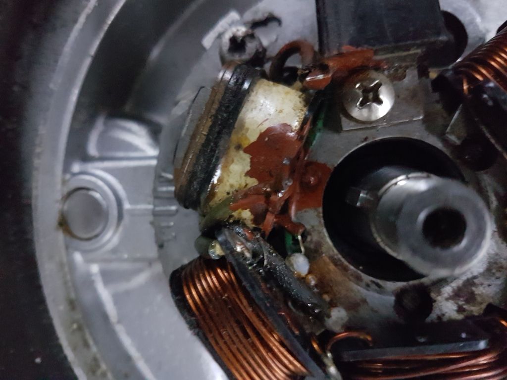 |
|
|
|
Post by pxguru on Jan 23, 2017 3:25:13 GMT
For a 125 that is reasonably standard the timing should be exactly on the 'IT' mark.
The stators are the same on both. Crumbling wires tell me that it is an older stator though. Nothing wrong with that just old fashioned wire. Solder on some new ones and it should be fine. Be sure the wire used is a multi stranded core, as it will break less easily.
|
|
|
|
Post by doulsy on Jan 24, 2017 20:54:40 GMT
For a 125 that is reasonably standard the timing should be exactly on the 'IT' mark. The stators are the same on both. Crumbling wires tell me that it is an older stator though. Nothing wrong with that just old fashioned wire. Solder on some new ones and it should be fine. Be sure the wire used is a multi stranded core, as it will break less easily. thanks |
|
|
|
Post by doulsy on Jan 29, 2017 21:02:04 GMT
pxguru? is that allready on the it mark? or should it be on the I before the T, look at this wirirng its a 5 wire and i cant even tell the colours lol, the t5 has a round plug with 3 wires on it, should 3 not go to the cdi or does one go back from the plug? 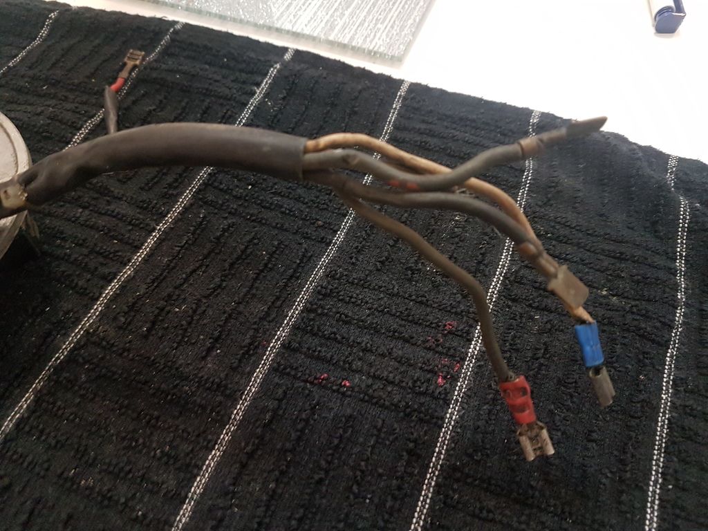 |
|
|
|
Post by doulsy on Jan 29, 2017 21:15:03 GMT
maybe the plug only has 2 wires, i only had a quick look and not really planned ahead till i have log book.
|
|
|
|
Post by pxguru on Jan 30, 2017 3:50:24 GMT
The wires are the same colours. You wouldn't believe it to look but they are. Those white plugs are not really good enough for the job. Had a few burn out and melt. I have no issue with cutting them off and using spades like this old stator does.
You should change all of those wires on the stator though. Don't think about keeping them. The old ones used to snap all the time, as I remember.
|
|
|
|
Post by rab on Jan 30, 2017 20:50:29 GMT
3 wires non battery 5 battery  just taken tx stator off and its 3 non battery one im putting in is a disk battery model stator and its 5. so you will have a choice later to convert to battery very easy if you want for dc horn or spots usb charger and so on |
|
|
|
Post by doulsy on Jan 30, 2017 21:02:01 GMT
3 wires non battery 5 battery just taken tx stator off and its 3 non battery one im putting in is a disk battery model stator and its 5. so you will have a choice later to convert to battery very easy if you want for dc horn or spots usb charger and so on pretty sure my p200e non battery has a 5 wire stator, would need to look back at photo's though, found this guide . linkcant find a kit, guess i will need to buy wiring. |
|
|
|
Post by rab on Jan 30, 2017 21:24:31 GMT
my tx is a p2 engine non battery 3 wire one to back 2 forward to loom its very possible its an upgraded stator or built with it in for the choice at factory or pre sale for upgrades when you choose options from new that way it would only need dc option rectifier to power a battery. beedspeed do the dc loom but it has startor on so a waste of money realy you only need the rectifier and to split one wire off into two at rectifier to feed the dc side
|
|
|
|
Post by doulsy on Jan 30, 2017 21:33:18 GMT
my tx is a p2 engine non battery 3 wire one to back 2 forward to loom its very possible its an upgraded stator or built with it in for the choice at factory or pre sale for upgrades when you choose options from new that way it would only need dc option rectifier to power a battery. beedspeed do the dc loom but it has startor on so a waste of money realy you only need the rectifier and to split one wire off into two at rectifier to feed the dc side you have blue and black going into loom and a few to cdi im sure. my p2 lay in a garden for 30 year so its not had upgrade, even using the original cdi |
|
|
|
Post by doulsy on Jan 30, 2017 21:35:33 GMT
yes 3 wires to cdi along with the green kill switch
|
|
|
|
Post by doulsy on Jan 31, 2017 21:41:02 GMT
can anyone point me in the right direction regarding stator wiring? amps ect, thought i could by a kit you could solder on but my google searches have been fruitless.
|
|
|
|
Post by sime66 on Feb 1, 2017 18:22:36 GMT
I’ve rewired lots of used stators now; it’s a pretty straightforward job; this one shown is a T5 stator, but it’s almost the same (just the black – loom ground – wire connects differently, but doesn’t have to) – my coloured blobs on stripped-stator photo show where to connect wires, part-copy of my schematic show where they go on the loom/scooter: 
Forget ALL old wiring; use a soldering iron to strip it.
Test HT and pickup coils directly on stator; replace them if not up to scratch
Identify which coil the new wiring needs to be resoldered to, and route wiring with reference to how it routes around coils, through and under stator body, and through tube in frame – get it right before soldering.
Resolder, test with multimeter, and shroud wires.
Crimp spades, solder and heat-shrink to red, white and green wires going to stator – they get pulled-about, so I crimp and solder them.
Leave bare, or fit plastic connector**, or fit spades to blue and black wires to loom.
It’s ready to fit, pass through frame, and connect to CDI and loom.
Rotate stator body to approximate timing with marks on stator and casings, but make sure you strobe later too (mark timing on casings for this).
**On an old set of (125/150) casings the tube is narrower, and the plastic connector block will not pass through it.
**With that in mind, and noting what pxguru said about those connectors burning out, it’s probably better to fit spades to black and blue; up till now I’ve tried to reuse or replace the plastic blocks, but maybe I won’t do that any more.
I did buy a repair kit for the first one I did, but I can’t find those any more, and it’s just as easy to just get the bits you need anyway:

A meter of each colour will do for two stators; there’s loads on Ebay, so are the LT and pickup coils if you need them – keep the copper plate and bracket off the old LT coil though; you’ll need to find a rivet too.
Scooterhelp says 16 – 18 gauge; 16gauge=1.5mm²=21A, 18gauge=1mm²=14A.
For a 120w stator @ 12v, it’s 10Amps (Ohm’s Law), but erring on the side of double-it-and-add-a-bit, (I think I used 16Amp multi but can’t find any quickly anyway), there’s 16gauge single-core multi-strand, 1.5mm², 21A (=252W) in all the colours you need, at .99p/metre here:
www.ebay.co.uk/itm/14A-21A-30A-12v-Automotive-Cable-1m-100m-Auto-Wiring-Loom-Marine-1-1-5-2-5mm-Amp-/251737702046?var=&hash=item3a9cbc7e9e:m:mAOOLDMgwCK3MGr9UXd5ykg
In fact I’ve just ordered myself some more………………
Any other questions; you should know to read old threads – I know I’ve posted all this a few times before.
|
|
|
|
Post by doulsy on Feb 1, 2017 20:08:36 GMT
I’ve rewired lots of used stators now; it’s a pretty straightforward job; this one shown is a T5 stator, but it’s almost the same (just the black – loom ground – wire connects differently, but doesn’t have to) – my coloured blobs on stripped-stator photo show where to connect wires, part-copy of my schematic show where they go on the loom/scooter:
Forget ALL old wiring; use a soldering iron to strip it.
Test HT and pickup coils directly on stator; replace them if not up to scratch
Identify which coil the new wiring needs to be resoldered to, and route wiring with reference to how it routes around coils, through and under stator body, and through tube in frame – get it right before soldering.
Resolder, test with multimeter, and shroud wires.
Crimp spades, solder and heat-shrink to red, white and green wires going to stator – they get pulled-about, so I crimp and solder them.
Leave bare, or fit plastic connector**, or fit spades to blue and black wires to loom.
It’s ready to fit, pass through frame, and connect to CDI and loom.
Rotate stator body to approximate timing with marks on stator and casings, but make sure you strobe later too (mark timing on casings for this).
**On an old set of (125/150) casings the tube is narrower, and the plastic connector block will not pass through it.
**With that in mind, and noting what pxguru said about those connectors burning out, it’s probably better to fit spades to black and blue; up till now I’ve tried to reuse or replace the plastic blocks, but maybe I won’t do that any more.
I did buy a repair kit for the first one I did, but I can’t find those any more, and it’s just as easy to just get the bits you need anyway:
A meter of each colour will do for two stators; there’s loads on Ebay, so are the LT and pickup coils if you need them – keep the copper plate and bracket off the old LT coil though; you’ll need to find a rivet too.
Scooterhelp says 16 – 18 gauge; 16gauge=1.5mm²=21A, 18gauge=1mm²=14A.
For a 120w stator @ 12v, it’s 10Amps (Ohm’s Law), but erring on the side of double-it-and-add-a-bit, (I think I used 16Amp multi but can’t find any quickly anyway), there’s 16gauge single-core multi-strand, 1.5mm², 21A (=252W) in all the colours you need, at .99p/metre here:
www.ebay.co.uk/itm/14A-21A-30A-12v-Automotive-Cable-1m-100m-Auto-Wiring-Loom-Marine-1-1-5-2-5mm-Amp-/251737702046?var=&hash=item3a9cbc7e9e:m:mAOOLDMgwCK3MGr9UXd5ykg
In fact I’ve just ordered myself some more………………
Any other questions; you should know to read old threads – I know I’ve posted all this a few times before.
thanks sime, yes your threads allways come up on google when im searching for stuff but sometimes they have to much info to take in  not a clue how to check coils or pick ups and i dont have a clue how to use a strope, i will tackle the rewiring though and bump this thread about timing when the time comes. |
|
|
|
Post by rab on Feb 4, 2017 9:08:59 GMT
sime66 is like a leeking book of know how and how to with all the stuff we dont think of i think hes an audio book a very good one at that if you can keep him away from guru then it goes a bit mental over weeks lol
|
|
|
|
Post by doulsy on Feb 4, 2017 13:57:19 GMT
my five wires arrived today, cant find my little gas soldering iron any where, hoping to give it a try later, what is the brown stuff that covers the solder connections?
|
|
|
|
Post by doulsy on Feb 4, 2017 20:40:09 GMT
my solderings skills are not very good, this is the best i could do, will i need to cover the soldered bits with something? 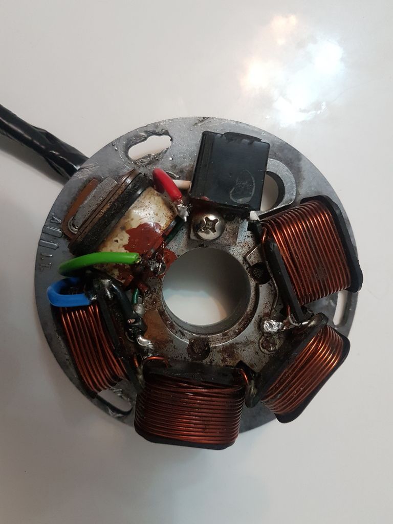 |
|
|
|
Post by sime66 on Feb 4, 2017 21:15:54 GMT
1st Feb, Doulsy said: "not a clue how to check coils or pick ups"
.......so; you found this out, or ignored the point?
Maybe you’ll get some more soldering practice before you’re finished……...
|
|
|
|
Post by doulsy on Feb 4, 2017 21:41:57 GMT
1st Feb, Doulsy said: "not a clue how to check coils or pick ups".......so; you found this out, or ignored the point? Maybe you’ll get some more soldering practice before you’re finished……... ignored it m8, not a first, did a google search and it never understood the stuff i found so yes. i have ignored this part |
|
|
|
Post by doulsy on Feb 4, 2017 21:54:52 GMT
1st Feb, Doulsy said: "not a clue how to check coils or pick ups".......so; you found this out, or ignored the point? Maybe you’ll get some more soldering practice before you’re finished……... ignored it m8, not a first, did a google search and it never understood the stuff i found so yes. i have ignored this part oh and thanks for the help |
|


 just taken tx stator off and its 3 non battery one im putting in is a disk battery model stator and its 5. so you will have a choice later to convert to battery very easy if you want for dc horn or spots usb charger and so on
 not a clue how to check coils or pick ups and i dont have a clue how to use a strope, i will tackle the rewiring though and bump this thread about timing when the time comes.